E-series Hardware Guide
168 ! CT1 and CE1 I/O Modules
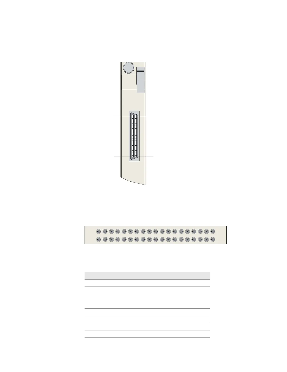
Figure 58: CE1 I/O module with Telco connectors
Figure 59 shows the location of the 20 pairs of BNC connectors on a balun panel.
The cables from the CE1 I/O module are plugged into the two 50-pin Telco
connectors on the other side of the panel.
Figure 59: Twenty-port balun panel
Table 40 and Table 41 list the pinout for the Telco connectors on each cable.
PIN 25
PIN 1
CE1
I/O
PIN 50
PIN 26
0-9
g013774
TX
RX
PORT
1021 3456789 111213141516171819
g013775
Table 40: Pinout of 50-pin Telco connector to ports 0–9
Pin Signal Pin Signal
1 Port 0 RX TIP 26 Port 0 RX RING
2 Port 0 TX TIP 27 Port 0 TX RING
3 Port 1 RX TIP 28 Port 1 RX RING
4 Port 1 TX TIP 29 Port 1 TX RING
5 Port 2 RX TIP 30 Port 2 RX RING
6 Port 2 TX TIP 31 Port 2 TX RING
7 Port 3 RX TIP 32 Port 3 RX RING
8 Port 3 TX TIP 33 Port 3 TX RING
9 Port 4 RX TIP 34 Port 4 RX RING