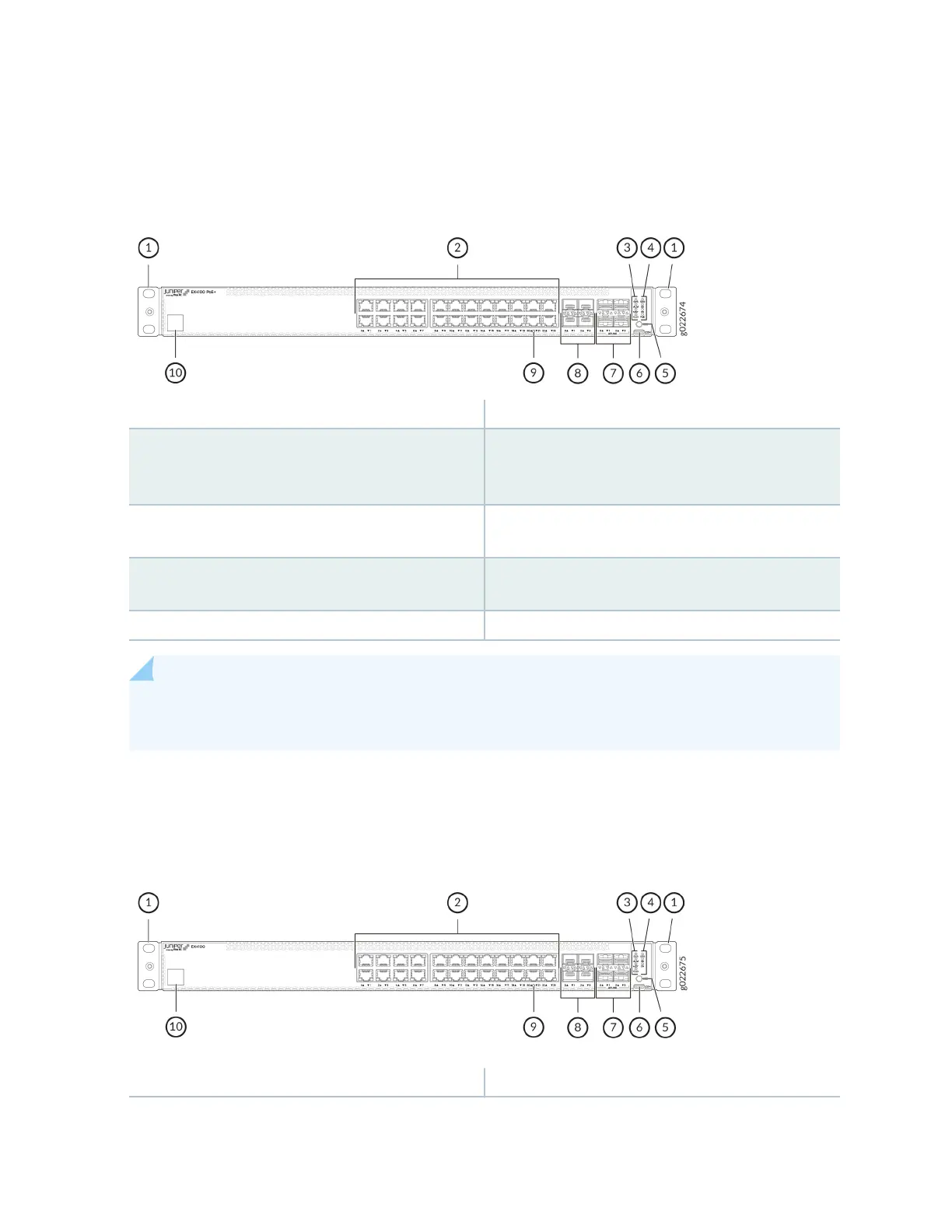
Figure 7 on page 6 shows the components on the front panel of the EX4100-24P switch.
Figure 7: Components on the Front Panel of the EX4100-24P Switch
1—
Front mounng brackets
6—
RS232 to USB Type-C console port
2—
10/100/1000BASE-T RJ-45 network ports.
These ports in EX4100-24P switches support
PoE+ (30 W by default).
7—
1GE/10GE SFP+ Uplink ports
3—
Chassis status LEDs (labeled SYS, ALM, MST,
and CLD)
8—
10GE/25GE SFP28 Virtual Chassis ports
4—
Port mode LEDs (labeled SPD, DX, EN, and
PoE)
9—
Reset buon
5—
Factory Reset/Mode buon
10—
Claim Code label
NOTE: Claim Code labels for 24 port EX4100 models are on the front panels; for 48 port
EX4100 models, Claim Code labels are on the rear panels.
Figure 8 on page 6 shows the components on the front panel of an EX4100-24T switch.
Figure 8: Components on the Front Panel of the EX4100-24T Switch
1—
Front mounng brackets
6—
RS232 to USB Type-C console port
6