2—
Sixteen 1/2.5 GE and thirty-two 1 GE BASE-
T RJ-45 network ports. These ports in
EX4100-48MP support PoE++ (90 W).
7—
1/10 GE SFP+ Uplink ports
3—
Chassis status LEDs (labeled SYS, ALM, MST,
and CLD)
8—
10/25 GE SFP28 Virtual Chassis ports
4—
Port mode LEDs (labeled SPD, DX, EN and
PoE)
9—
Reset buon
5—
Factory Reset/Mode buon
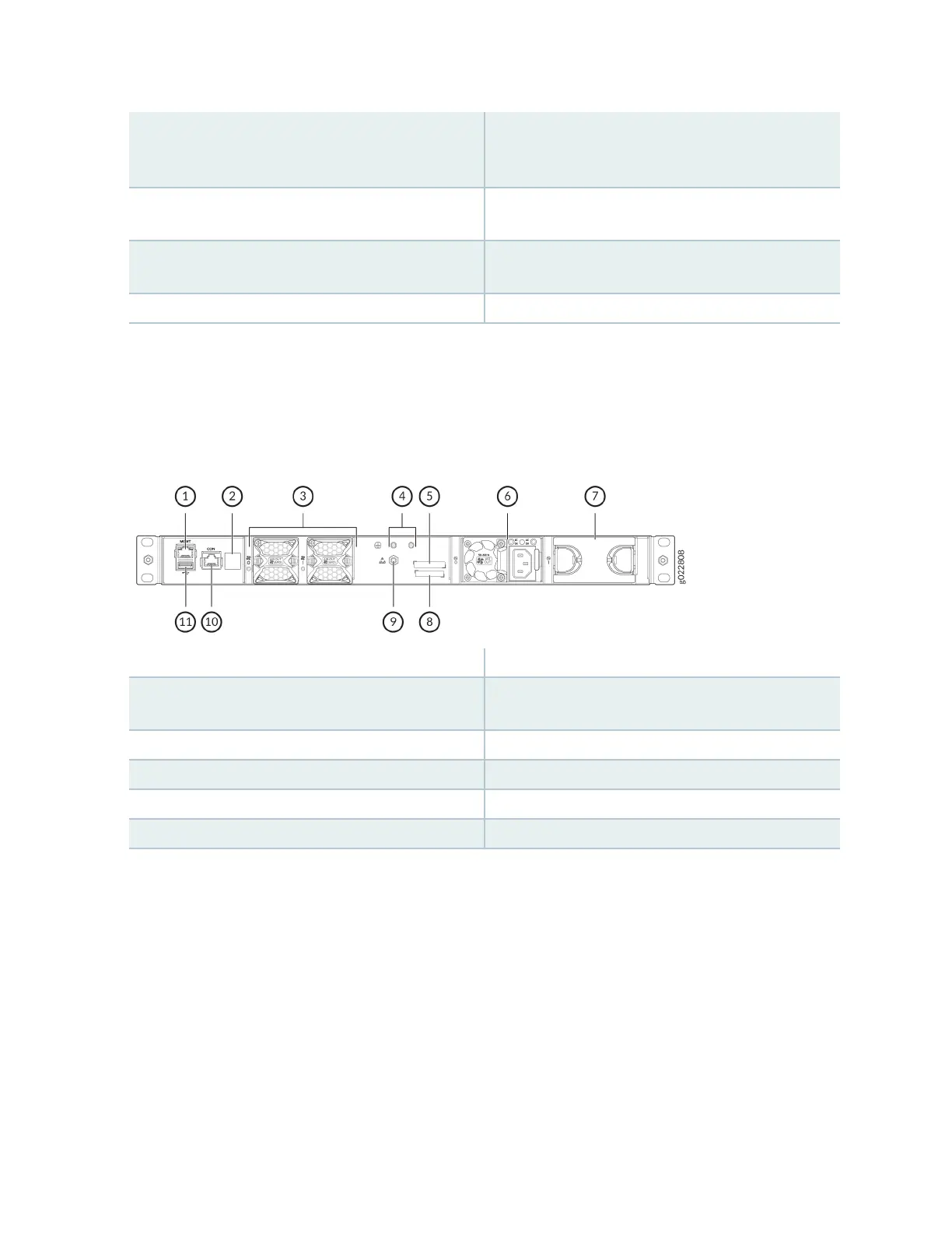
Figure 30 on page 16 shows the components on the rear panel of the EX4100-24MP and
EX4100-48MP switch.
Figure 19: Components on the Rear Panel of the EX4100-24MP and EX4100-48MP Switch
1—
RJ-45 management port (labeled MGMT)
7—
Empty slot for power supply
2—
Claim Code label (for EX4100-48MP
switches)
8—
Serial number
3—
Fan modules
9—
Electrostac discharge (ESD) point
4—
Protecve earthing terminal
10—
RJ-45 console port (labeled CON)
5—
CLEI code label
11—
USB 2.0 Type A port
6—
AC power supply
12