• The loss of chassis cluster links which causes an interface monitoring failure.
• An error in an SPU or NPU.
• Failure of the spu-monitoring or cold-sync-monitoring processes.
• A chassis cluster IP monitoring failure.
LINK/ACT LED, one for each of the two ports CHASSIS CLUSTER CONTROL 0 and
CHASSIS CLUSTER CONTROL 1:
•
Green (ickering)–Chassis cluster control port link is acve.
•
O–No link.
ENABLE LED, one for each of the two ports CHASSIS CLUSTER CONTROL 0 and
CHASSIS CLUSTER CONTROL 1:
•
Green–The chassis cluster control port is enabled.
• O–The chassis cluster control port is disabled.
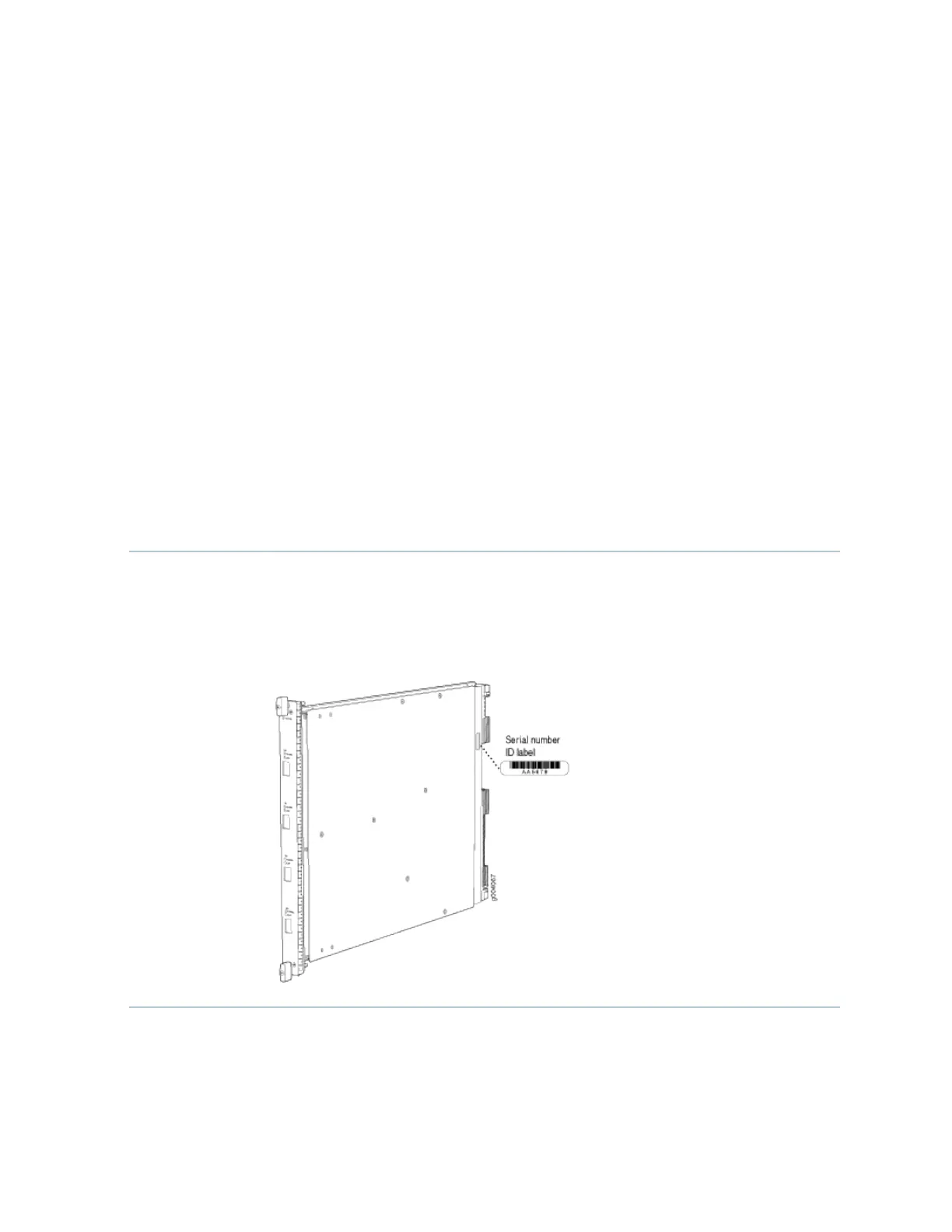
Serial Number
Locaon
The serial number label is located as shown in Figure 3 on page 13.
Figure 3: Serial Number Label (IOC Shown, Other Cards Similar)
13

 Loading...


