1-14 (No.MB014)
3.1.9 Removing the power transformer assembly
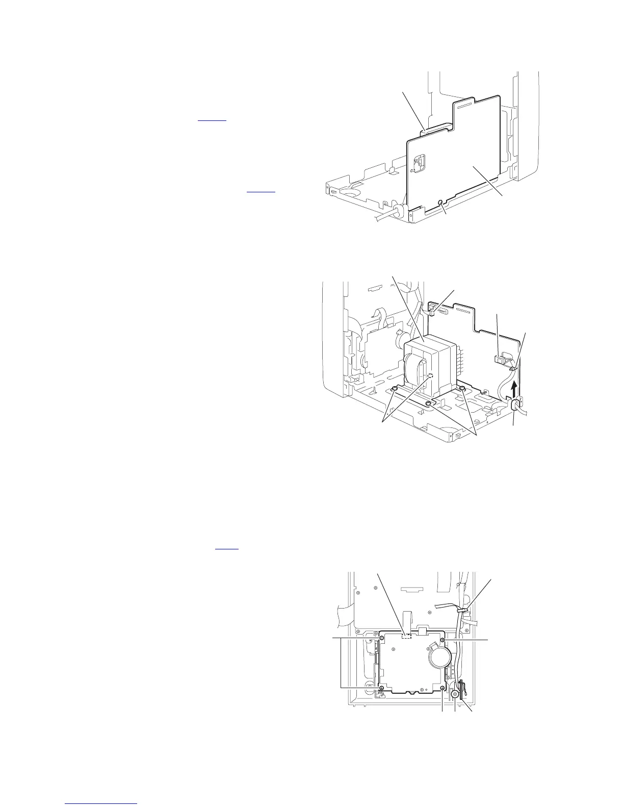
(See Fig 24, 25)
• Prior to performing the following procedure, remove the metal
cover, the CD changer mechanism assembly, the rear panel,
the main board and the bridge board / regulator board.
(1) Remove the screw N attaching the primary board.
(2) Disconnect the wire from connector CN231
on the primary
board.
(3) Remove the four screws O attaching the power transform-
er assembly.
(4) Detach the cord stopper from the base chassis upward.
REFERENCE:
When disconnecting the power cord from connector CN250
on
the primary board, remove the fixing band.
Fig.24
Fig.25
3.1.10 Front panel assembly
• Prior to performing the following procedure, remove the metal
cover, the CD changer mechanism assembly and the front
panel assembly.
3.1.11 Removing the cassette mechanism assembly
(See Fig.26)
(1) Disconnect the card wire from connector CN33
on the head
amplifier & mechanism control board.
(2) Remove the two screws P, and the two screws Q attach-
ing the cassette mechanism assembly.
3.1.12 Removing the headphone board
(See Fig.26)
(1) Remove the screw R and pull out the headphone board
backward.
(2) Cut off the band.
Fig.26
Power transformer
assembly
Primary board
N
Primary board
CN231
CN250
Cord stopper
FIxing band
Power transformer
assembly
O
O
Head amplifier &
mechanism control board
CN33
Headphone board
P
Q
QR
Band
 Loading...