(No.MB014)1-19
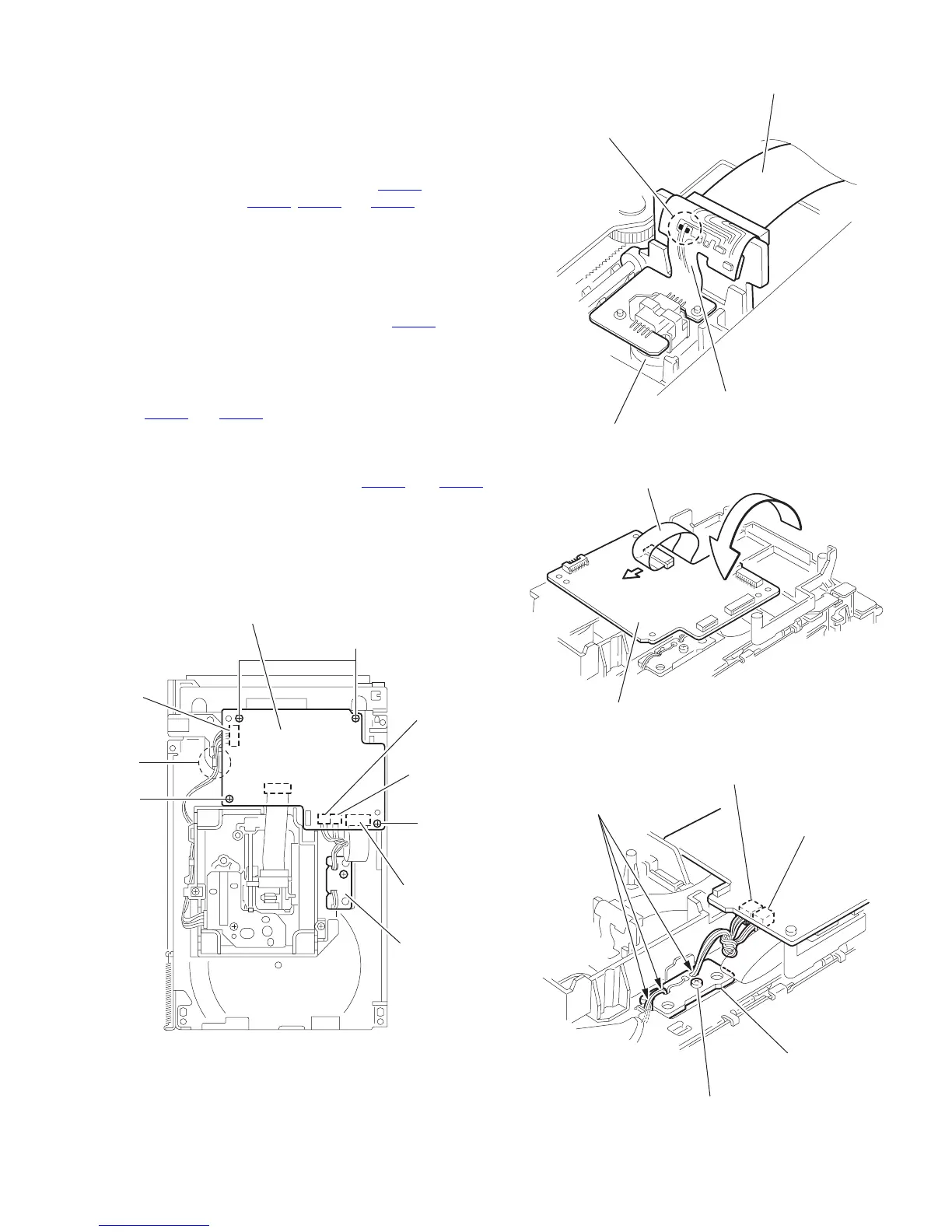
3.2.2 Removing the servo control board
(See Fig.6 ~ 9)
Caution:
Solder the short-circuit point on the pickup before disconnect-
ing the card wire extending from the pickup. If you do not follow
this instruction, the pickup may be damaged.
(1) Disconnect the card wire from connector CN251
and each
wire from connector CN252
, CN253 and CN602 on the ser-
vo control board on the bottom of the body. Disconnect the
wire from joint d.
(2) Solder the short round point on the flexible board of the pick
up.
(3) Remove the four screws B and turn the servo control board
as shown in the figure.
(4) Disconnect the card wire from connector CN601
on the
servo control board.Caution: Unsolder the short-circuit
point after reassembling.
Caution:
When reassembling, twist the wires to be connected to con-
nector CN252
and CN253 twice.
3.2.3 Removing the switch board
(See Fig.9)
(1) Disconnect the wires from connector CN252
and CN253
on the servo control board.
(2) Remove the screw C attaching the switch board.
(3) Release the wires from the slot e of the switch board.
Caution:
When reassembling, let the wires through the slot e of the
switch board and twist them twice.
Fig.6
Fig.7
Fig.8
Fig.9
B
B
B
d
CN602
CN251
Switch board
Servo control board
CN252
CN253
Pickup
Flexible board
Short round
Card wire
CN601
Servo control board
Card wire
CN252
e
C
Servo control board
CN253
Switch board
 Loading...