1-12 (No.MB014)
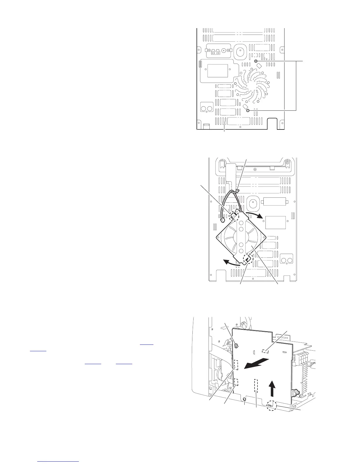
3.1.6 Rmoving the fan assembly
(See Fig.17, 18)
• Prior to performing the following procedure, remove the metal
cover, the CD changer mechanism assembly and the rear pan-
el.
(1) Cut the band with for fan wire holder.
(2) Remove two screws G on the rear panel.
(3) Rotate fan assembly in clockwise direction to release fan
assembly from rear panel (joints c).
Fig.17
Fig.18
3.1.7 Removing the main board
(See Fig.19)
• Prior to performing the following procedure, remove the metal
cover, the CD changer mechanism assembly and the rear pan-
el.
(1) Cut off the band.
(2) Disconnect the card wires from connector CN44
and
CN870
on the main board.
(3) Remove the screw H attaching the main board.
(4) Disconnect connector CN217
and CN311 on the main
board outward and release from the base chassis (joint d)
upward.
Fig.19
G
Rear panel
c
c
Fan assembly
Band
CN870
CN44
CN311
Main board
CN217
Band
H
d
 Loading...