MULTICAL® 803
Kamstrup A/S · Technical description · 5512-2360_A1_GB_02.2019
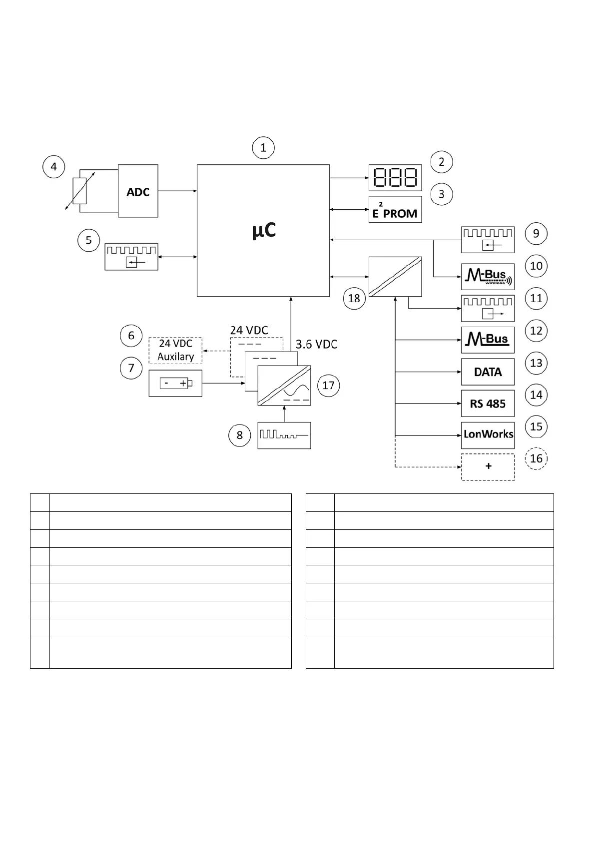
1.2 Electronic structure
The electronic construction of MULTICAL® 803 is shown in the block diagram below. The module slots in MULTICAL®
803 can be used with up to four communications modules that in addition to data communications also contain
pulse inputs or pulse outputs. An overview of the available communication modules can be found in paragraph 11.
Microcontroller
Wireless M-Bus
Display, eight-digit seven-segment + symbols
Pulse outputs
Non-volatile memory, EEPROM
M-Bus
Temperature sensors, Pt100 or Pt500, 2- or 4-wire
Data communication
Pulse inputs for flow sensors
RS 485, Modbus and BACnet
24 VDC supply for analog outputs (option)
LonWorks
Backup battery, 2 x A-cells
… and even more communication options
High-power SMPS, 24 VAC/VDC or 230 VAC
Galvanic separation, power supplies
Pulse inputs for additional water and electricity
meters
Galvanic separation, communication modules
Note: The arrows in the figure indicate the signal direction.