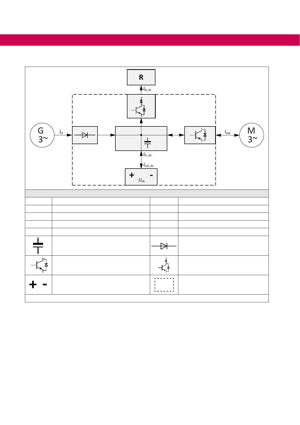
3.2 Block diagram of energy ow in the device
Legend
U
in Input voltage range Iout_dc Output current DC connection
I
in Mains input current IB_dc Braking current PB connection
I
in_dc Input current DC connection Iout Output current motor
U
dc Operating voltage range DC connection R Braking resistor
G Generator M Motor
DC link Input circuit
Inverter Braking transistor
DC connection Drive converter
Figure 1: Block diagram of energy ow in the device
28
BLOCK DIAGRAM OF ENERGY FLOW IN THE DEVICE

 Loading...


