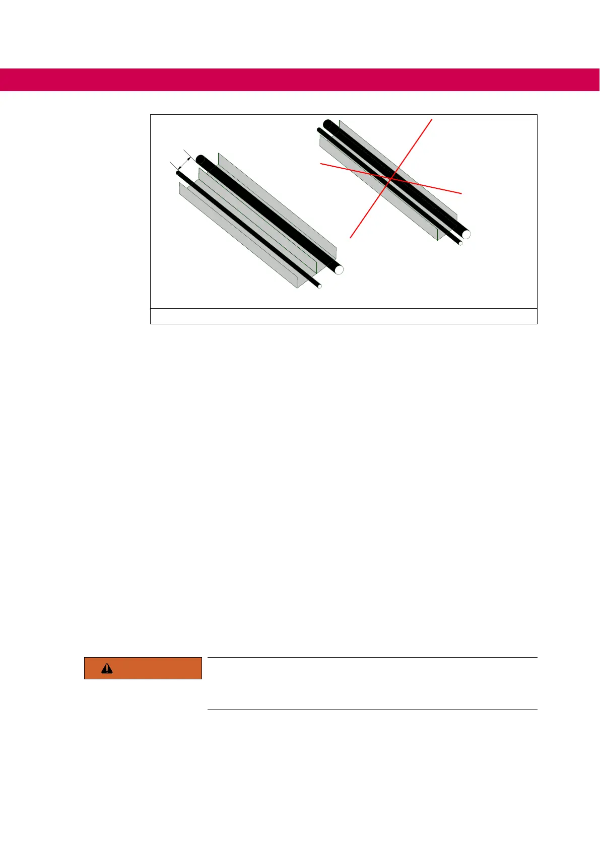
>230 V AC
>230 V AC
≤24 V DC
≤24 V DC
min.
200
Figure 16: Laying the cables
6.1.2 Connection of the shield connection
• Cable shields must not be used for power supply.
• A cable shield must not assume the function of an N or PE conductor.
• Always lay cable shields over a large surface.
• Do not extend the cable shield by unshielded wire connections to the earthing point.
This reduces the shielding effect by up to 90 %.
• Lay the cable shield over a large surface directly after the entry point of the control
cabinet.
6.1.3 Connection of the protective earth
• The drive converter or the control cabinet in which the drive converter is installed
must be connected to protective earth at the installation site.
• Use a protective earth conductor that corresponds at least half the cross-section of
the cables used to supply the power terminals.
• An earthing stud is provided at the drive converter for connecting the motor protec-
tive earth.
• Theresistanceoftheprotectiveearthshouldbe0.1Ωorless.
• According to EN 61800-5-1, the minimum cross-section of the protective earth con-
ductor must comply with the local safety regulations for protective earth conductors
for equipment with high leakage current.
WARNING
Indirect contact
Only with a correctly connected protective earth conductor the device
fulllstherequirementsforprotectionagainstindirectcontact.
64
ELECTRICAL INSTALLATION

 Loading...


