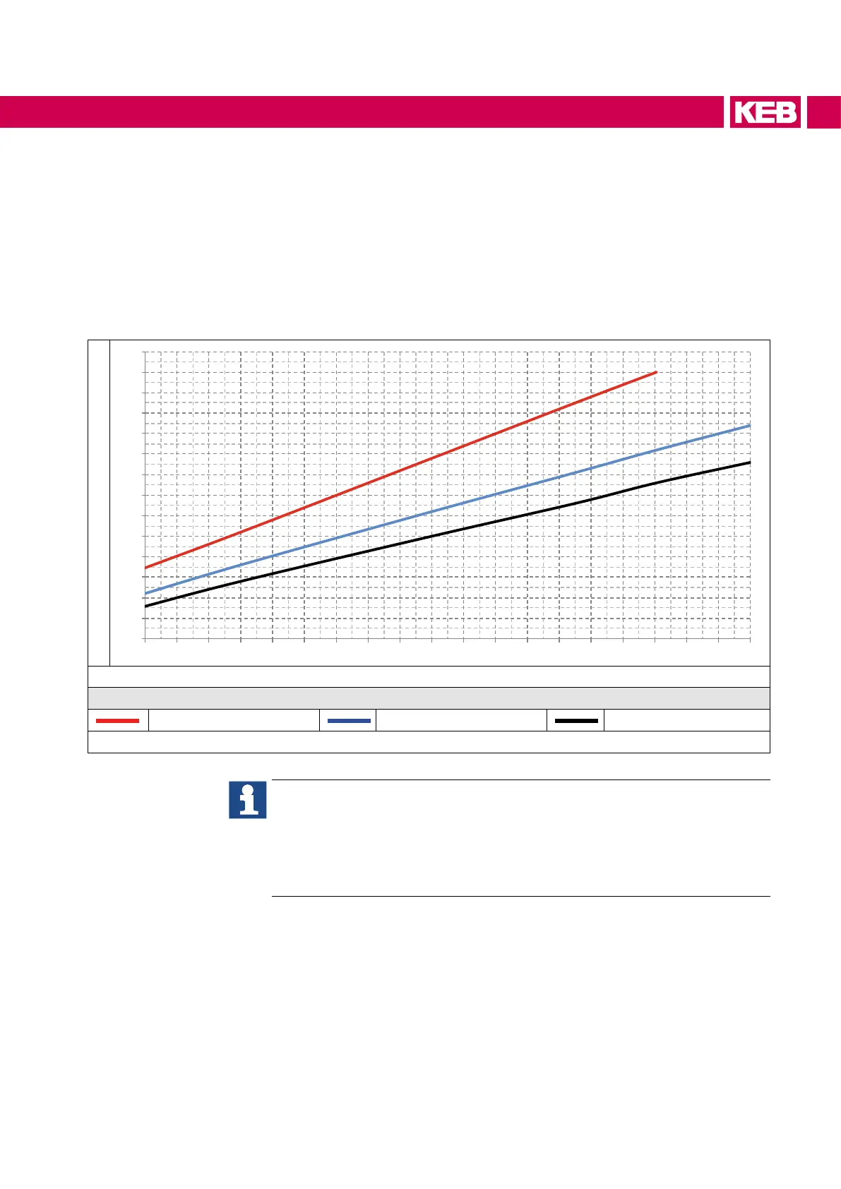
10.3 Power dissipation of the 400V class at rated operation
The following diagram shows the total power dissipation as a function of the output cur-
rent per module at
• different switching frequencies
• 50 Hz output frequency
• 25 °C ambient temperature
10.3.1 Power dissipation of different switching frequencies
Total power dissipation (Pv) in kW
1 ,0
1 ,5
2 ,0
2 ,5
3 ,0
3 ,5
4 ,0
4 ,5
5 ,0
5 ,5
6 ,0
6 ,5
7 ,0
7 ,5
8 ,0
1 90 210 230 250 270 290 310 330 35 0 370 390 410 430 450 470 490 510 530 550 570
Output current (Iout) in A
Legend
8 kHz 4 kHz 2 kHz
Figure 41: Power dissipation of different switching frequencies 400V class
Determination of power dissipation with parallel connected modules:
► Divide the output current by the number of modules
► Determine the power dissipation from the upper diagram with the deter-
mined output current for a module
► Multiply the power dissipation with the number of modules
97
CHARACTERISTICS

 Loading...


