5.2.3 Series connection of liquid coolers
• Volumeowasafunctionoftotalpowerdissipationandtemperaturedifference.
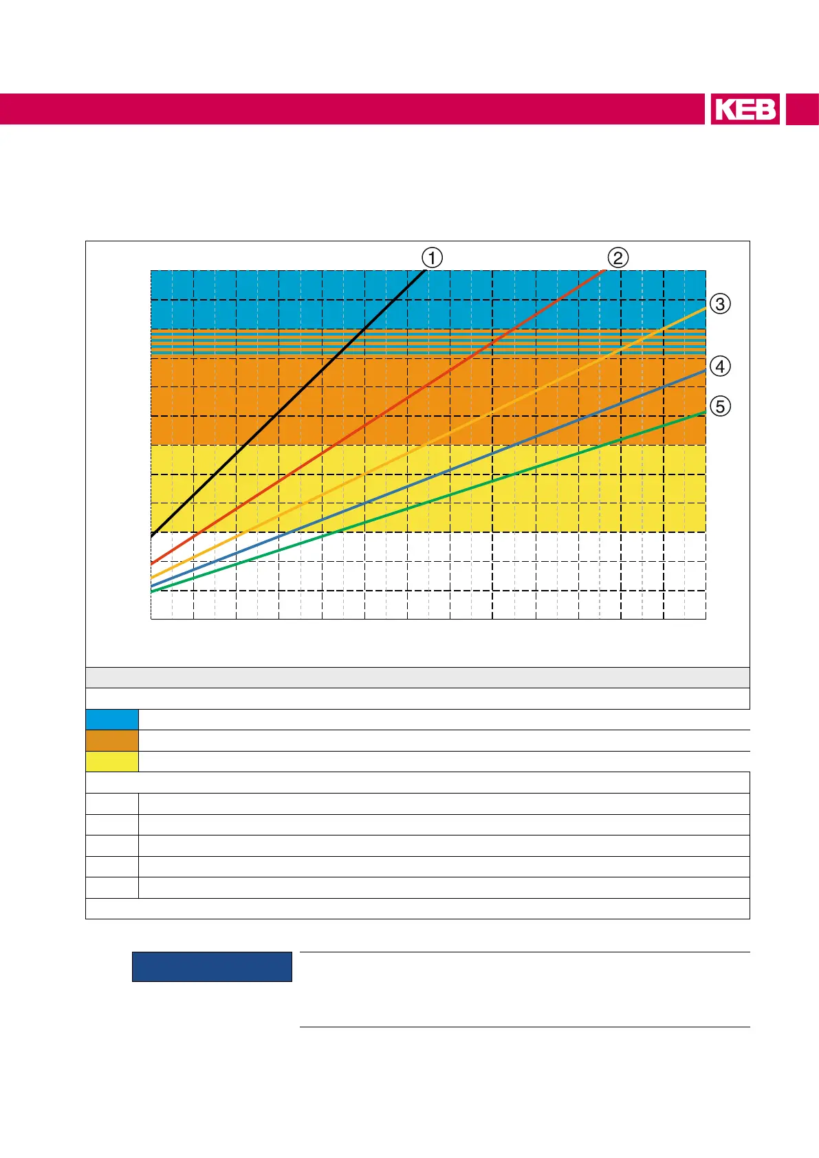
• The diagram below applies to the series connection of liquid coolers.
Temperature dierence ∆T in K
0
1
2
3
4
5
6
7
8
9
10
11
12
2 3 4 5 6 7 8 9 10 11 12 13 14 15
Total power dissipation Pv in kW
Legend
Recommended working range
Master / Slave / Slave ΔT = 9...12 K
Master / Slave ΔT = 6...10 K
Single Drive ΔT = 3...6 K
Volume ow
1 10 l/min
2 15 l/min
3 20 l/min
4 25 l/min
5 30 l/min
Figure 14: Volume ow and temperature difference for series connection
ATTENTION
• Series connection of liquid-cooled devices with stainless steel
tubes is not permitted, since the total system pressure can increase
above 10 bar.
• => Pressure drop aluminium heat sink with stainless steel tubes.
61
OPERATION OF LIQUID-COOLED DEVICES

 Loading...


