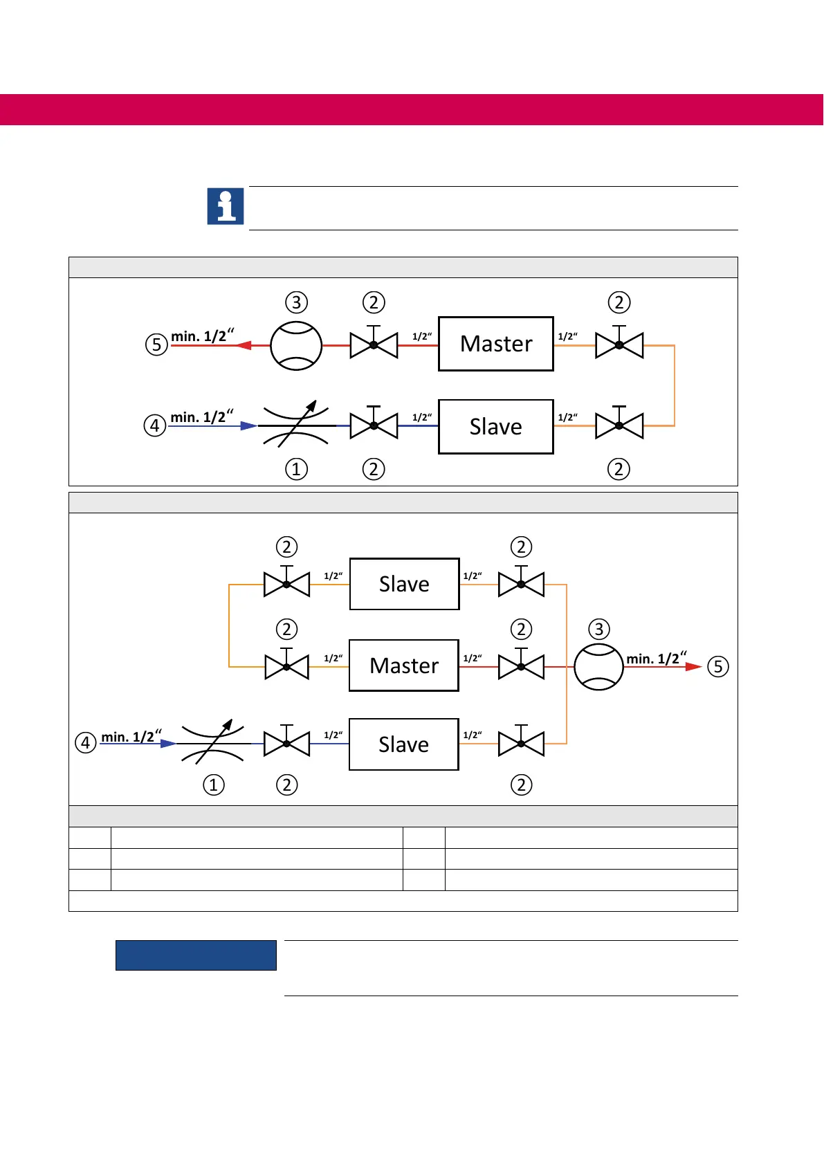
4.3.2 Connection diagram series connection cooling circuit
This connection scheme is only an installation proposal and does not replace
professional planning and execution!
Coolant connection for a master / slave system
⑥
⑥
Coolant connection for a master / slave / slave system
⑥
⑥
⑥
Legend
1 Throttle valve 10...40 l/min 4 Flow entire system
2 Ball valve / stop valve 5 Returnowentiresystem
3 Volumeowmeter 6 Drive converter
Figure 10: Connections to the coolant series connection
ATTENTION
Only parallel connection of the coolant circuit is permissible for alumini-
um heat sinks with stainless steel tubes.
52
MECHANICAL INSTALLATION

 Loading...


