4.4 Parallel connection of the coolant circuit
4.4.1 General instructions
• The connection of the coolant circuit as a parallel version is also possible in rated
operation. Mandatory for special applications.
• Thetotalvolumeowtobeselecteddependsonthesizeofthedevice,theoutput
current at rated operation and the resulting power dissipation for the drive converter
system.
• Thecorrelationbetweentotalpowerdissipation,volumeowandtemperaturedif-
ference are shown in the diagram Parallel connection of liquid coolers and must be
within the recommended operational range.
ATTENTION
• Themaximumtemperaturedifference(ΔT)betweenowandreturn
owmaynotexceed7K.
• Ifthevolumeow(above30l/minpermodule)isselectedtoolarge,
increases the risk of erosion in the liquid cooler.
• ThecoolingowmustalwaysbestartedbeforestartingtheKEB
COMBIVERT.
• Theuseofavolumeowmeterandatemperaturemonitoringis
mandatory required.
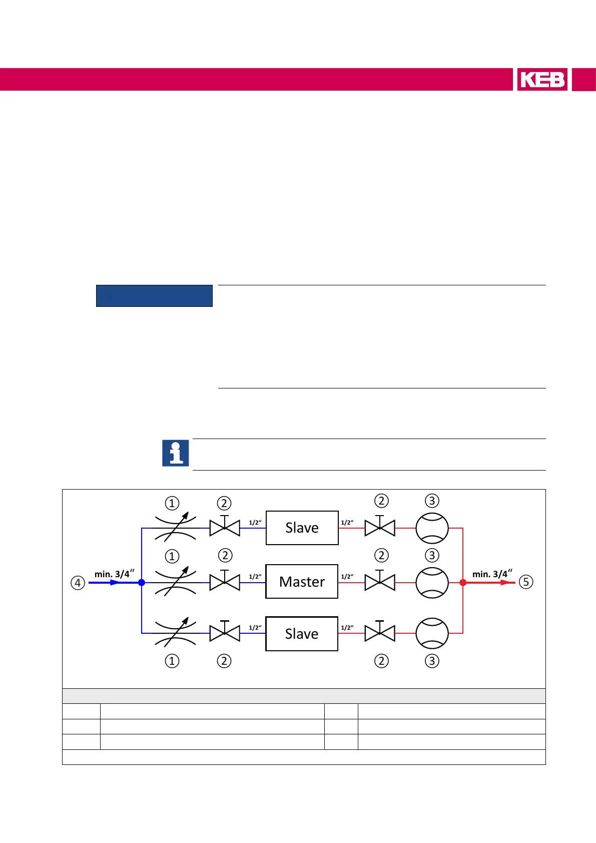
4.4.2 Connection scheme parallel connection of the cooling circuit
This connection scheme is only an installation proposal and does not replace
professional planning and execution!
⑥
⑥
⑥
Legend
1 Throttle valve 10...40 l/min 4 Flow entire system
2 Ball valve / stop valve 5 Returnowentiresystem
3 Volumeowmeter 6 Drive converter
Figure 11: Connections to the coolant parallel connection
53
MECHANICAL INSTALLATION

 Loading...


