5.2 Diagrams of the cooling design
5.2.1 Pressure drop aluminium extrusion casting heat sink
• Thecurvecharacteristicdescribedbelowisvalidfor25°CowtemperatureandAntifrogen
N 52 %.
• Iftherearehigherowtemperatures,thepressuredropinthesystemdecreases.
• This also applies to cooling medium such as water or another glycol mixture.
• A glycol mixture from Clariant in a ratio of 52 % or 33 % is recommended.
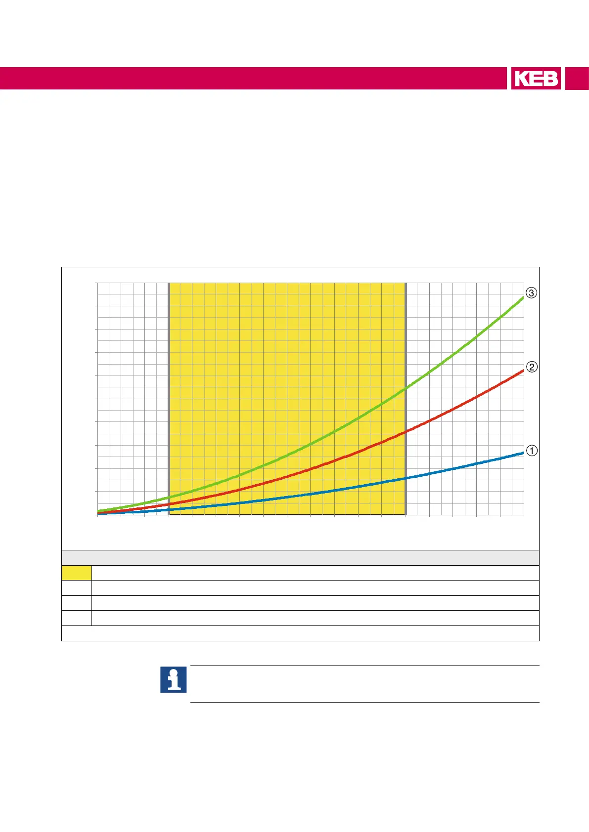
Pressure drop in bar
0,0
0,4
0,8
1,2
1,6
2,0
2,4
2,8
3,2
3,6
4,0
4 6 8 10 12 14 16 18 20 22 24 26 28 30 32 34 36
38
40
Volumeowinl/min
Legend
Recommended working range: 10...30 l/min
1 Single Drive
2 Series connection master / slave system
3 Series connection master / slave / slave system
Figure 12: Pressure drop of the heat sink as a function of the volume ow
The selection of the connection diagram (series or parallel connection) of the
cooling circuit depends on the total power dissipation of the drive converter
system.
59
OPERATION OF LIQUID-COOLED DEVICES

 Loading...


