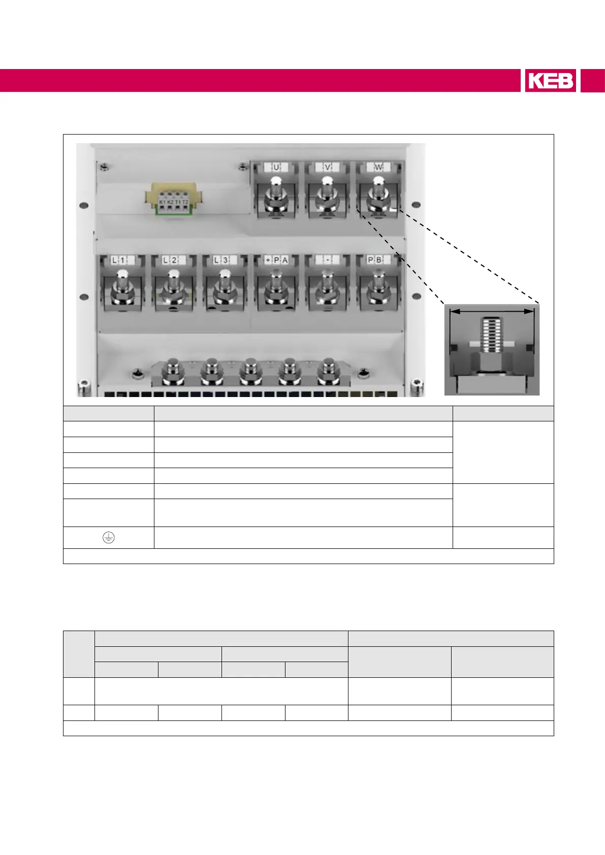
6.2 Connection terminals power unit
Terminal width
Terminal Function No.
1)
L1, L2, L3
Mains connection
1
U, V, W
Motor connection
+PA, PB
Connection for braking resistor
+PA, –
Connection for regenerative unit
T1, T2
Connection for temperature sensor (only single drive / master)
2
K1, K2
Monitoring braking transistor (connection values => Technical
Data)
Connection for shielding /earthing 1
Figure 17: Connection terminals of the power circuit
1) The assignment of the numbers refers to the table =>Permitted cable cross-sections and tightening
torques of the terminals.
6.2.1 Permitted cable cross-sections and tightening torques of the terminals
No.
Cable cross-section Maximum tightening torque
mm² AWG/MCM
Nm lb inch
min max min max
1*)
M12 stud for ring thimble max. 2 ring thimbles=>
Cable cross-sections
35 310
2 0.2 4 24 AWG 10 AWG 0.6 5.3
Table 19: Permissible cable cross-sections and tightening torques of the terminals
*)
Input studs/nuts shall be connected with UL listed ring connectors (ZMVV).
65
ELECTRICAL INSTALLATION
 Loading...


