6-4 Model 2790 SourceMeter
®
Switch System User’s Manual
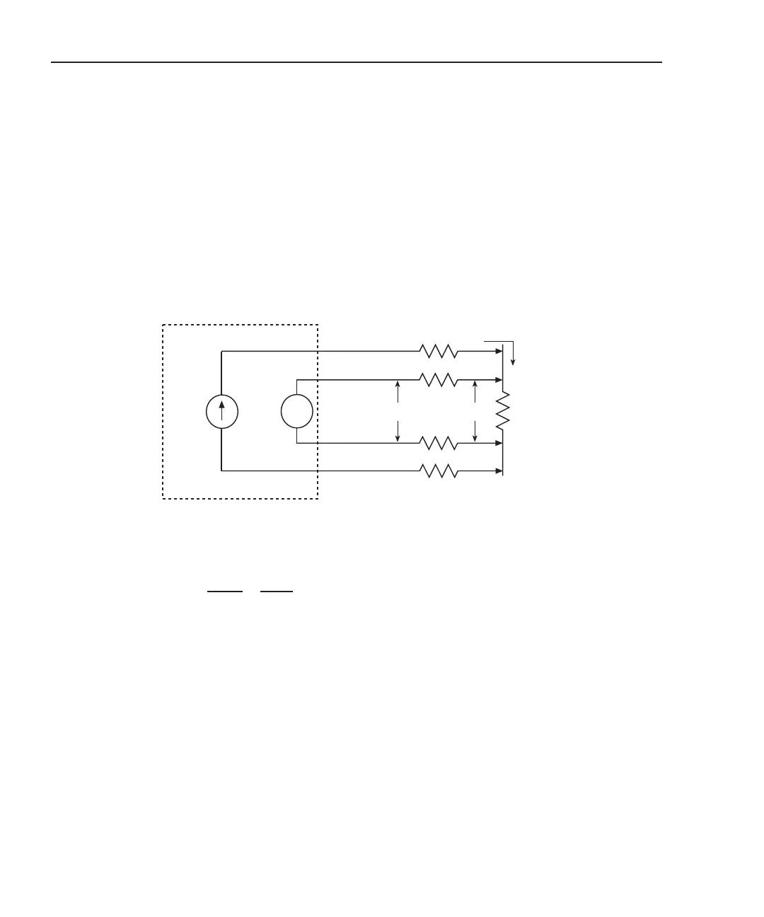
The 4-wire (Kelvin) connection method shown in Figure 6-2 should be used for low resis-
tance measurements. With this configuration, the test current is forced through R
DUT
through one set of test leads, while the voltage is measured through a second set of test
leads (called sense leads).
Due to the high impedance of the DMM of the Model 2790, negligible current will flow
through the sense leads. Since the voltage across the sense leads will be negligible, the
voltage measured by the DMM (V
MEAS
) is essentially the same as the voltage across the
DUT (V
R
).
Figure 6-2
Using
ΩΩ
ΩΩ
4 function to measure resistance
I
SOURCE
(1mA)
RLEAD
RMEAS =
V
MEAS
ISOUR
Keithley 2790
v
RLEAD
RDUT
VMEAS
Input HI
Input LO
VMEAS VR
VMEAS = Voltage measured by 2790 DMM
VR = Voltage across RDUT
= R
DUT
=
V
R
ISOUR
Ω4 Function Selected
R
LEAD
Sense HI
R
LEAD
Sense LO
Because sense current is negligible, VMEAS = VR
Therefore:
Test Current