SECTION 6
Thmy of opmtion
1
\L
Switch “c” closed Signal
“A” and “B” open Phase
L
switch “B” closf!d
zero
“A” and “c” open
Phase
.L
Switch “A” closed
Reference
“B” and “c” open Phase
.L
Calculate
a Reading
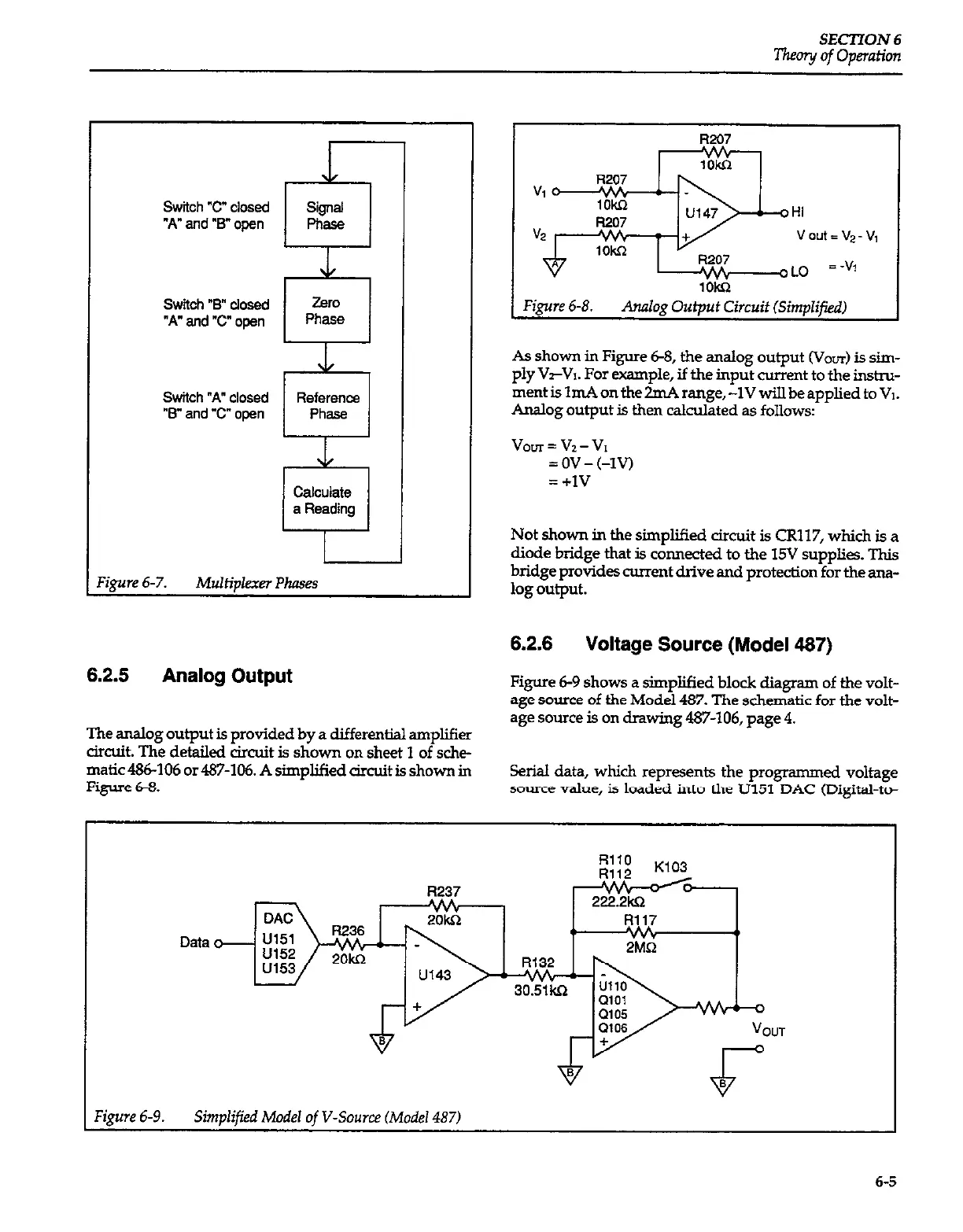
6.2.5
Analog Output
The analog output is provided by a differential amplifier
circuit. The detailed circuit is shown on sheet 1 of sche-
matic486-106 or487-106. A simplified circuit is shown in
Figure 6-S.
HI
vout=v*-v,
LO =-vj
lOkL2
Figure 6-8. Analog Output Circuit &mplifiedJ
As shown in Figure 68, the analog output (Vo~r) is sim-
ply &-VI. For example, if the input current to the instm-
ment is ImA on the ZmA range, -lV will be applied to VI.
Analog output is then calculated as follows:
voLrr=v2-VI
= ov - (-Iv)
= +I!7
Not shown in the simplified circuit is CR117, which is a
diode bridge that is connected to the 15V supplies. Tbis
bridge provides current drive and protection for the ana-
log output.
6.2.6 Voltage Source (Model 467)
Figure 6-9 shows a simplified block diagram of the volt-
age source of the Model 487. The schematic for the volt-
age source is on drawing 487-106,
page 4.
Serial data, which represents the programmed voltage
source value, is loaded into the U151 DAC (Digital-to-
Data
R237
222.2k.Q
1 Figure 6-9.
Simplified Model of V-Source (Model 487)
6-5