SEC’UON 3
Front Panel Operation
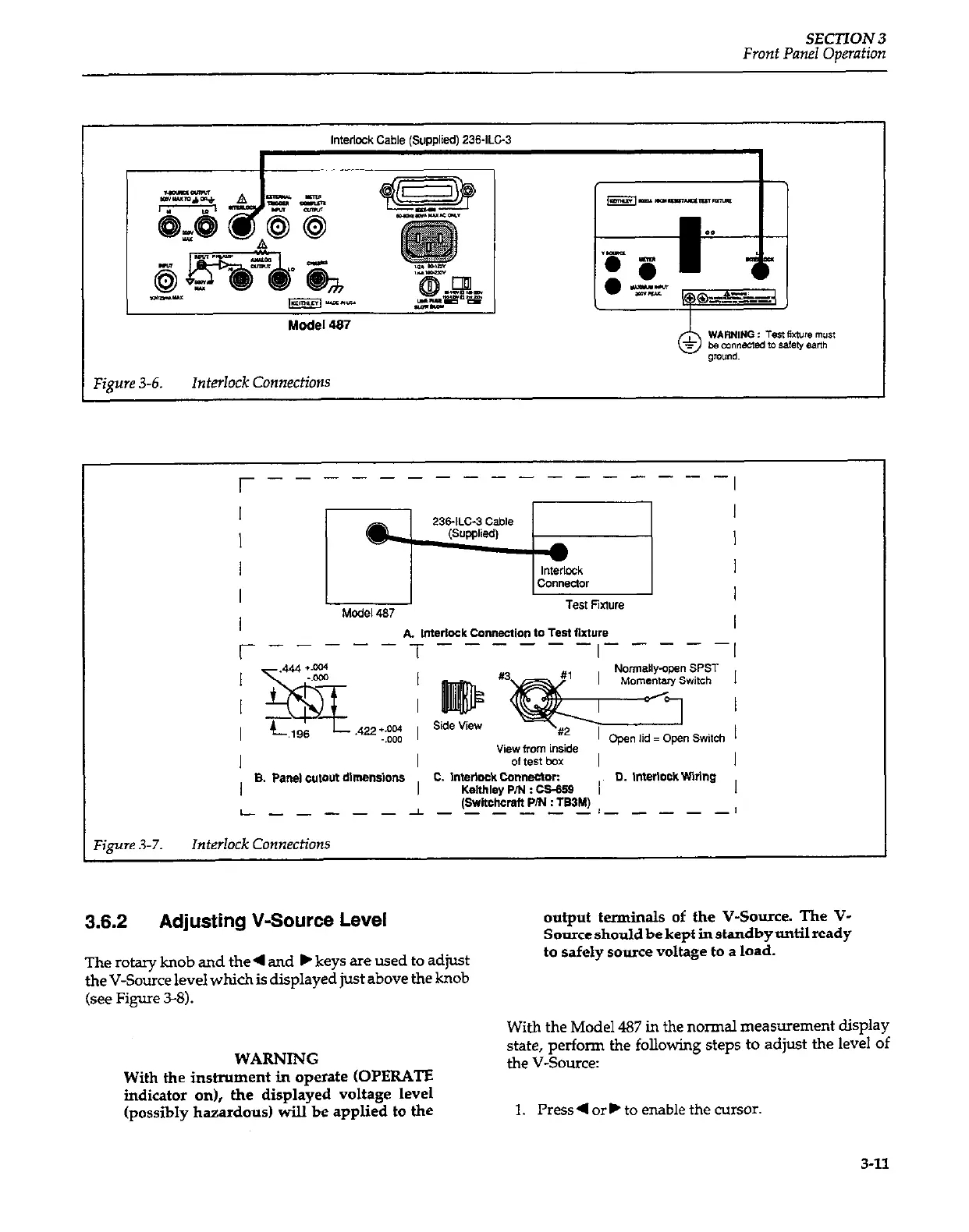
Interlock Cable ISUDDlied) 236ILC-3
F&ye 3-6. Interlock Connections
;-----T------,-----;
A Imerlock Connection 10 Test Sxture
8. Pane, w,ovt dlmenslons
c. l”wlclck co”“ectc.r:
I
0. merlock wmng
Kelthley P/N : cs-659
(swnchcmfl PIN : TS3M)
L------l-- ____ /__---I
,‘igure 3-7.
Interlock Connections
3.6.2
Adjusting V-Source Level
output terminals of the V-Source. The V-
Source should be kept in standby until ready
The rotary knob and the 4 and b keys are used to adjust
the V-Source level which is displayed just above the knob
(see Figure 3-8).
to safely source voltage to a load.
WARNING
With the inshument in operate (OPERATE
indicator on), the displayed voltage level
(possibly hazardous) will be applied to the
With the Model 487 in the normal measurement display
state, perform the following steps to adjust the level of
the V-Source:
1. Press 4
orb to
enable the cursor.
3-11