Keysight B1500A Configuration and Connection Guide
3-5
Connection Guide for Wafer Prober
SMU/GNDU connection with prober
3.1.2 SMU connections
An SMU terminal is shown in Figure 3-4.
CAUTION Never connect the Guard terminal to any output, including circuit common, chassis
ground, or any other guard terminal. Doing so will damage the SMU.
Figure 3-4 SMU terminal
Non-Kelvin connection
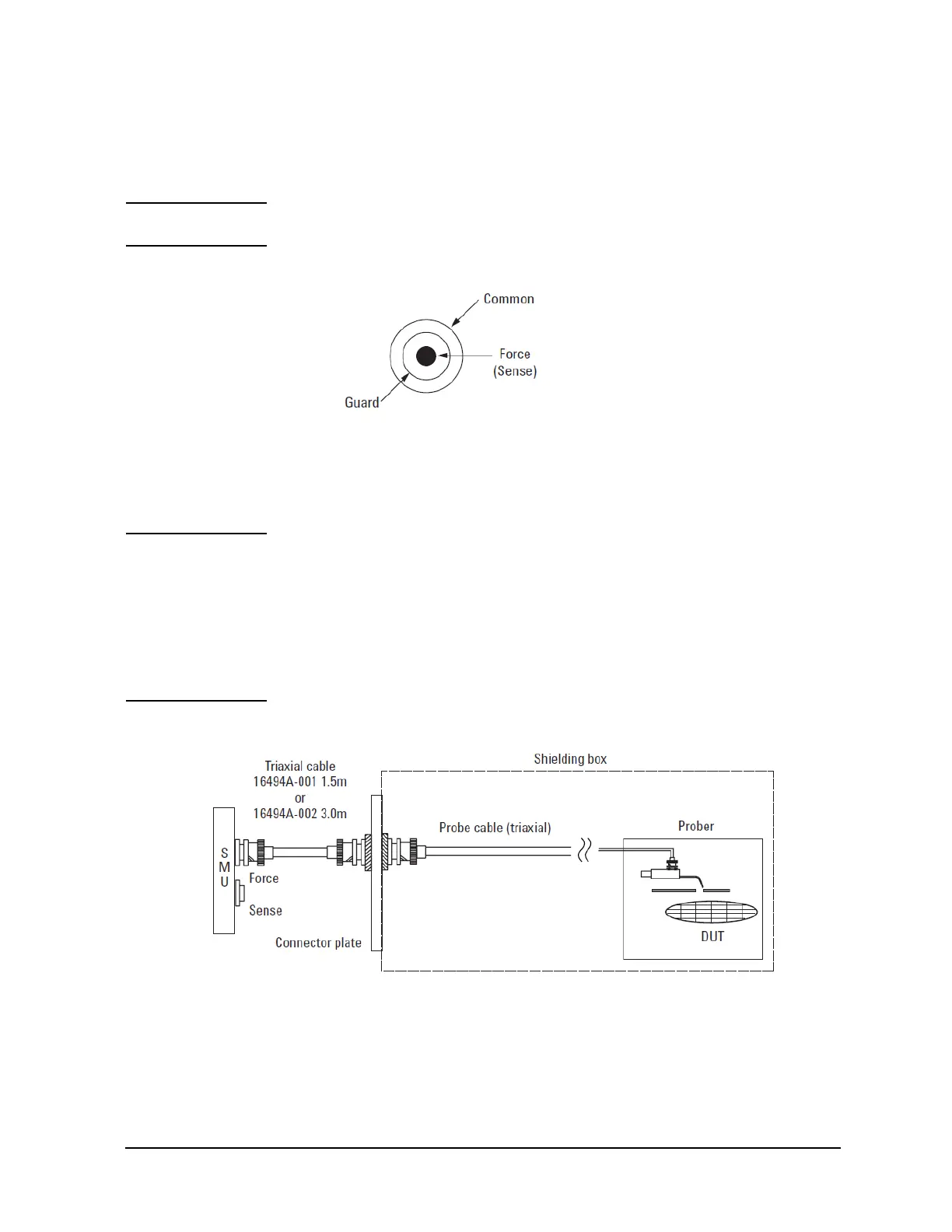
These instructions apply when all connections are non-Kelvin. Connect the Keysight
16494A triaxial cables between the SMU and the Connector plate. Connect the triaxial
connector on the probe cable as shown in Figure 3-5. For parts information, see Table 3-4.
NOTE Making non-kelvin connection
The Force terminals can be used to force and measure DC voltage or current. If you want to
simplify the cable connections, open the Sense terminals and connect the Force terminals
only to the connector plate by using the triaxial cables. If user makes the Kelvin
connection, use both Force and Sense terminals. Connecting the Force and Sense lines
together at the terminal of the device under test minimizes the measurement error caused
by the residual resistance of the connection cables. The Kelvin connection is effective for
the low resistance measurement and the high current measurement.
Figure 3-5 Example of an SMU non-Kelvin connection

 Loading...


