Keysight B1500A Configuration and Connection Guide
3-17
Connection Guide for Wafer Prober
SCUU and ASU
3.4.2 ASU connection
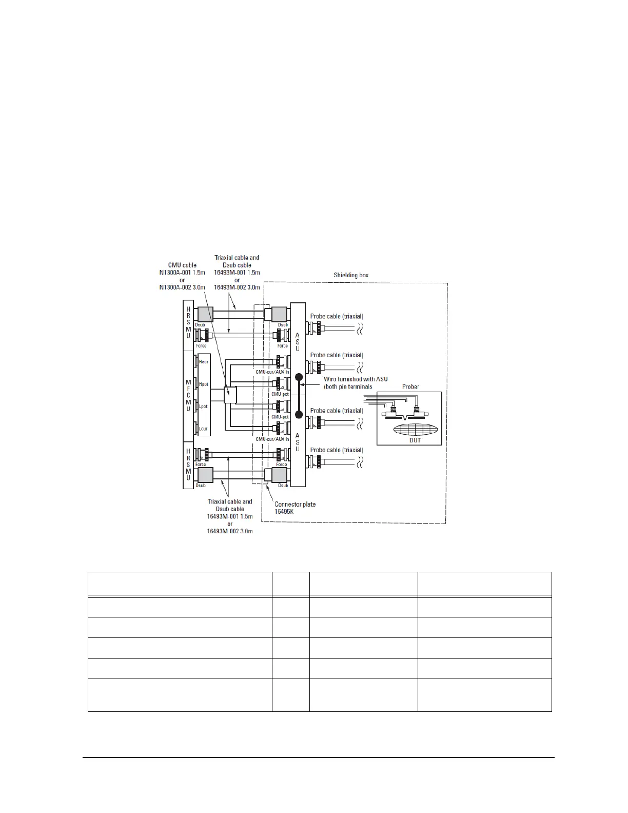
Each ASU has one D-sub control cable, one triaxial cable, and (optionally) two coaxial
cables connected to it. The cables can be connected to the ASU inside the shielding box
through the 16495K plate. The ASU outputs should be connected to the DUT by using
triaxial cables as shown in Figure 3-18. When making IV measurements with the SMUs,
all measurements are Kelvin. The SENSE line information is fed back to the SMU via the
D-sub cable. When making CV measurements, the four-terminal pair (4TP) connecti
ons
are correctly
terminated inside of the ASUs. The ASUs also allow for a current return path
between the outer conductors to stabilize the series inductance and improve accuracy. Yo
u
must
connect the furnished wire between the two ASUs to enable this feature.
Figure 3-18 Example of an ASU connection
Table 3-8 Item number information for ASU connection with B1500A
Description Qty Product Number Part number
Triax and D-sub cable for ASU (1.5 m) 2 16493M-001 N/A
Triax and D-sub cable for ASU (3.0 m) 2 16493M-002 N/A
CMU cable for B1500 (1.5 m) 1 N1300A-001 N/A
CMU cable for B1500 (3.0 m) 1 N1300A-002 N/A
Connector plate with universal cable
holder
1 16495K N/A

 Loading...


