3-26
Keysight B1500A Configuration and Connection Guide
Connection Guide for Wafer Prober
Interlock circuit
3.6 Interlock circuit
The interlock circuit is designed to prevent electrical shock wen a user touches the
measurement terminals.
CAUTION You must install an interlock circuit on a shielding box to prevent hazardous voltage when
the door of the shielding box is open.
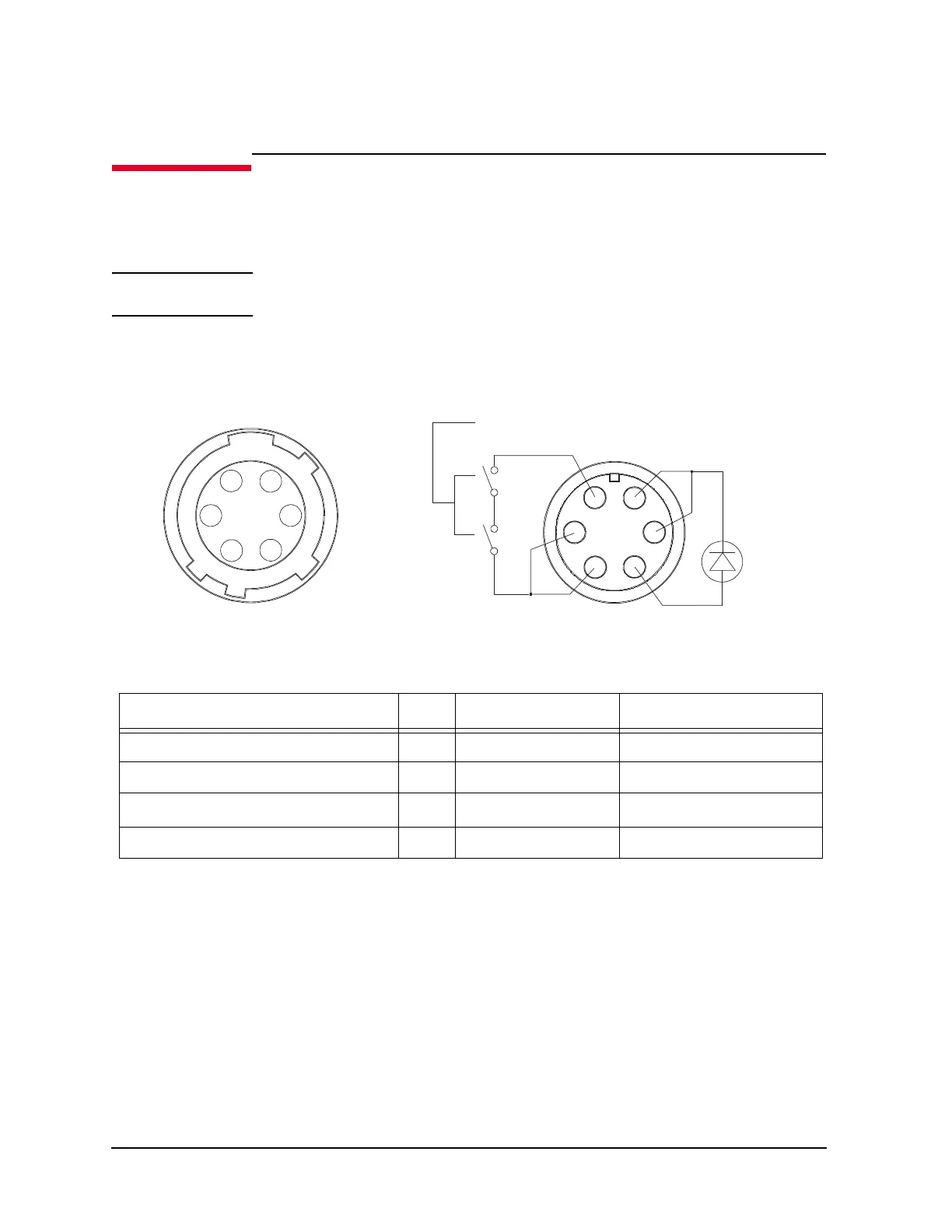
Figure 3-28 shows the pin assignments of the interlock connector that should be mounted
on a connector plate or test fixture.
Figure 3-28 Interlock connector pin assignments
Table 3-12 Recommended parts for interlock circuit
3.6.1 Installing the interlock circuit
Prepare the required parts listed in Table 3-12. And install the interlock circuit as shown
below.
1. Make mounting hole for the interlock connector. See Figure 3-30 for dimensions.
2. Mount two mechanical switches on your shielding box, so that the switches close wh
en
the do
or of the shielding box is closed, and open when the door is opened. Fo
r the
dim
ensions of the switch, see Figure 3-31 below.
3. Mount an LED on your shielding box. For the dimensions of the LED, see Figure 3-29.
Description Qty Product Number Part number
Interlock connector (6 pin, female) 1 N/A 1252-1419
Interlock micro switch 1 N1254A-402 3101-0302 or 3131-3241
LED (V
F
≅ 2.1 V@ I
F
= 10 mA) 1 N/A 1450-0641
Wire (24 AWG, 600 V) 1 N/A 8150-5680
1
2
34
5
6
Plug side View
Interlock Switch
Wiring Side View
LED
1
2
3
4
5
6

 Loading...


