Keysight B1500A Configuration and Connection Guide
3-25
Connection Guide for Wafer Prober
WGFMU and RSU
These instructions apply when DC probes are used on Prober.
• Connect a SSMC short open cable between the Gate DC probe and the
well DC probe,
and
set the DC probes to the appropriate place. Then,
the black sleeve plug must be the
Gate side. This
electrically connects the Well probe needle, Well probe shield, an
d Gate
probe shiel
d together.
• Connect a SSMC short-open cable between the Drain DC probe and the Source DC
probe, and set the DC probes to the appropriate place. Then, the black sleeve
plug must
be the Drain side. Th
is electrically connects the Source probe needle, Source prob
e
sh
ield, and Drain probe shield together.
• Connect the last SSMC short-open cable between the Well DC probe
and the Source
DC probe, a
nd set the DC probes to the appropriate place. Then, the black sleeve
plug
mu
st be the Source side. This electrically connects the Well probe needle, Well prob
e
shiel
d, and Source probe shield together.
• Connect a SMA-SSMC cable between a RSU (ex: RSU1) and the Drain DC probe.
And set the Drain DC probe to the appropriate place.
• Connect the other SMA-SSMC cable between the other RSU (ex: RSU2) and the Gate
DC probe. And set the Gate DC probe to the appropriate place.
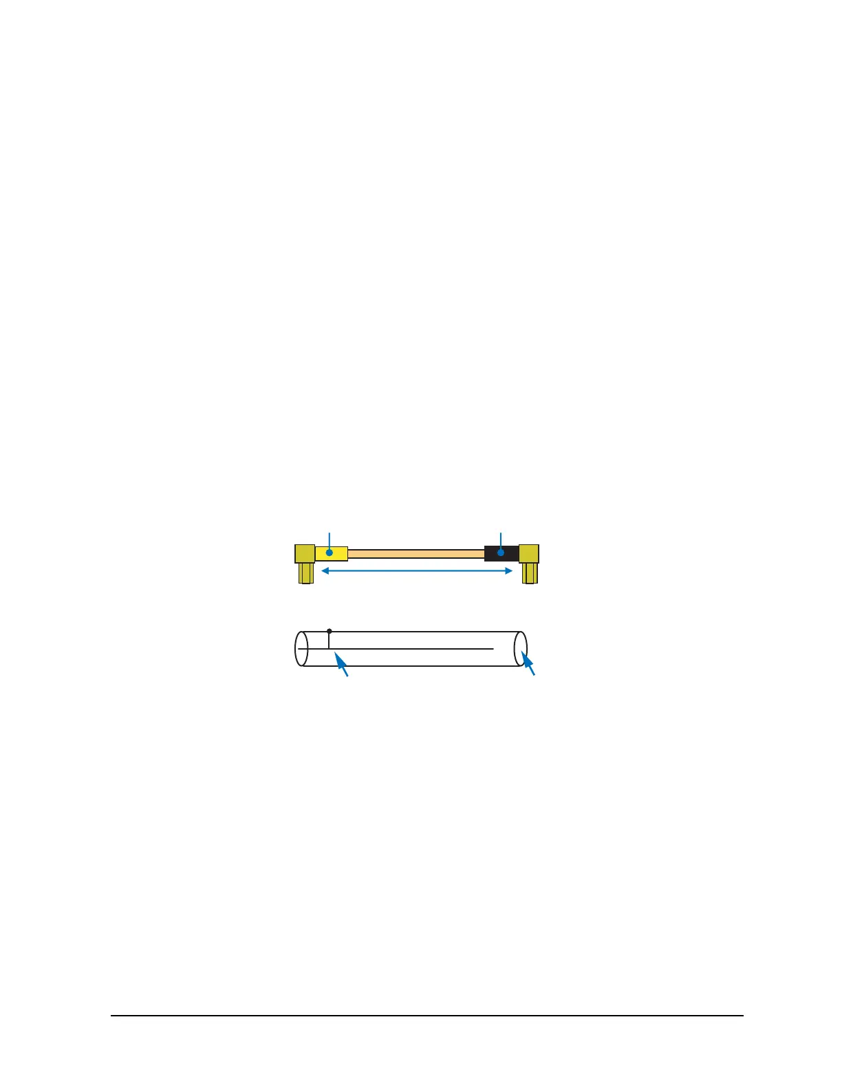
Figure 3-27 SSMC Short-Open Cable
50 mm or 75 mm
Black
SSMC(plug)
SSMC(plug)
Yellow
Signal line and shield are shorted. no signal pin

 Loading...


