3- 56 Keysight B1500A User’s Guide, Edition 14
Installation
Capacitance Compensation When Using Switching Matrix
To obtain compensation coefficients
Obtain the compensation coefficients as shown below.
1. Select the measurement frequency (Fmeas) used for the capacitance
measurement of a device under test (DUT), and set it to the MFCMU. The
coefficients must be measured at the same frequency.
2. Perform the MFCMU open calibration at the measurement terminal. Optionally,
perform short calibration if you want.
3. See Table 3-10 and Figure 3-23, and set the MFCMU.
4. Connect the path/cable corresponding to C3H (DATA07) shown in Figure 3-22
to the MFCMU. Then measure and record the R, L, and C values.
5. Connect the path/cable corresponding to C3L (DATA08) to the MFCMU. Then
measure and record the R, L, and C values.
6. If you use the connector plate, perform the following procedure.
a. Connect the path/cable corresponding to C2H (DATA05) to the MFCMU.
Then measure and record the R, L, and C values.
b. Connect the path/cable corresponding to C2L (DATA06) to the MFCMU.
Then measure and record the R, L, and C values.
Table 3-10 R, L, C Measurement Conditions
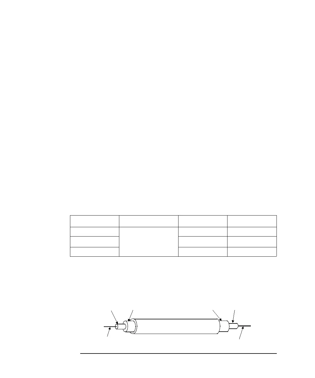
Figure 3-23 Compensation Coefficient Measurement Terminals of Extended Cables
Parameter Frequency Function Terminals
R
1 kHz to 5 MHz
a
a. R, L, C of all coefficients must be measured with the same frequency setting.
A and B
LSERIES
see note
b
b. For triaxial cable, connect B to F directly, and measure L between A and E.
For coaxial cable, ignore E and F, and connect B to D directly, and measure
L between A and C.
C PARALLEL A and C
FORCE or SENSE (A)
FORCE or SENSE (B)
Insulator
Triaxial Cable
GUARD (C) GUARD (D)GROUND (F)GROUND (E)