1. Connect the interface cable from the RP7900 unit to the SDS unit.
2. Connect the output of the RP7900 series to the input of the SDS unit.
3. Connect the output of the SDS unit to the device under test (the load).
4. If remote sensing is used, do NOT bundle the sense wire-pair together with the load leads; keep
the load wires and sense wires separate.
5. Install the bus bar safety covers. Depending on how the units are wired, you may need to remove
the bus bar cut-outs from the safety covers.
Connections with Paralleled Units
The limiting factor as to how many Keysight RP7900 units you can connect to one SDS unit is the
current rating of the SDS relays, which is 60 A. For example, you can connect one 500 V, 10 kW unit
and one 500 V, 5 kw unit to one SDS unit and still be within the maximum current rating of 60 A.
l In a master/slave configuration, connect the SDS interface cable to the master RP7900 unit.
l For detailed connection information for paralleled units, refer to Multiple Unit Connections.
l If remote sensing is being used, connect the sense leads of both RP7900 units to the RPS sense
terminals on the SDS unit.
l If multiple RPS units are used in a paralleled group, each 60 A group will require its own dedicated
SDS unit.
External Control Connections
Several customer-configurable functions are available on the rear panel of the SDS (see Controlling
the SDS Using Externally Wired Controls). The connectors and pin-out functions are described as
follows:
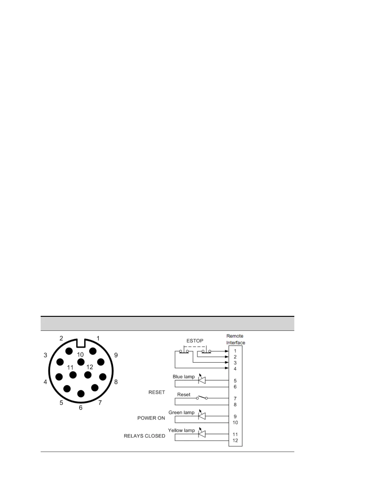
Remote Interface (M12) Connector
Rear panel pinout view Typical connections
Appendix A Keysight SD1000A Safety Disconnect System
306 Keysight RP7900 Series Operating and Service Guide

 Loading...


