Inductive Load Boundary for Current Priority Mode
EQUIPMENTDAMAGE You must protect the solid-state output relays from damage
with load inductance greater than 12.5 μH or twisted load leads longer than 15
meters (each wire). You can increase this length by paralleling additional twisted load
leads. To minimize the di/dt and resulting voltage across the relays, make sure that
the output current has been downprogrammed to zero before turning the output off.
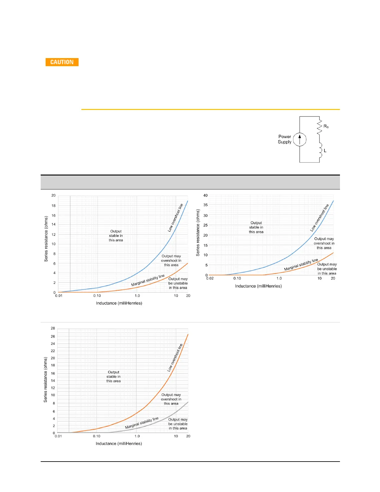
The following figures show the boundary limitations for inductive loads (L)
with series resistance (Rs) when operating in current priority mode.
Operation below the marginal stability line may result in output instability.
Note that increased load resistance allows increased output inductance.
500 V units 950 V units
500 V,10 kW unit
950 V,10 kW unit
500 V,5 kW unit
Keysight RP7900 Series Operating and Service Guide 57
1 Quick Reference

 Loading...


