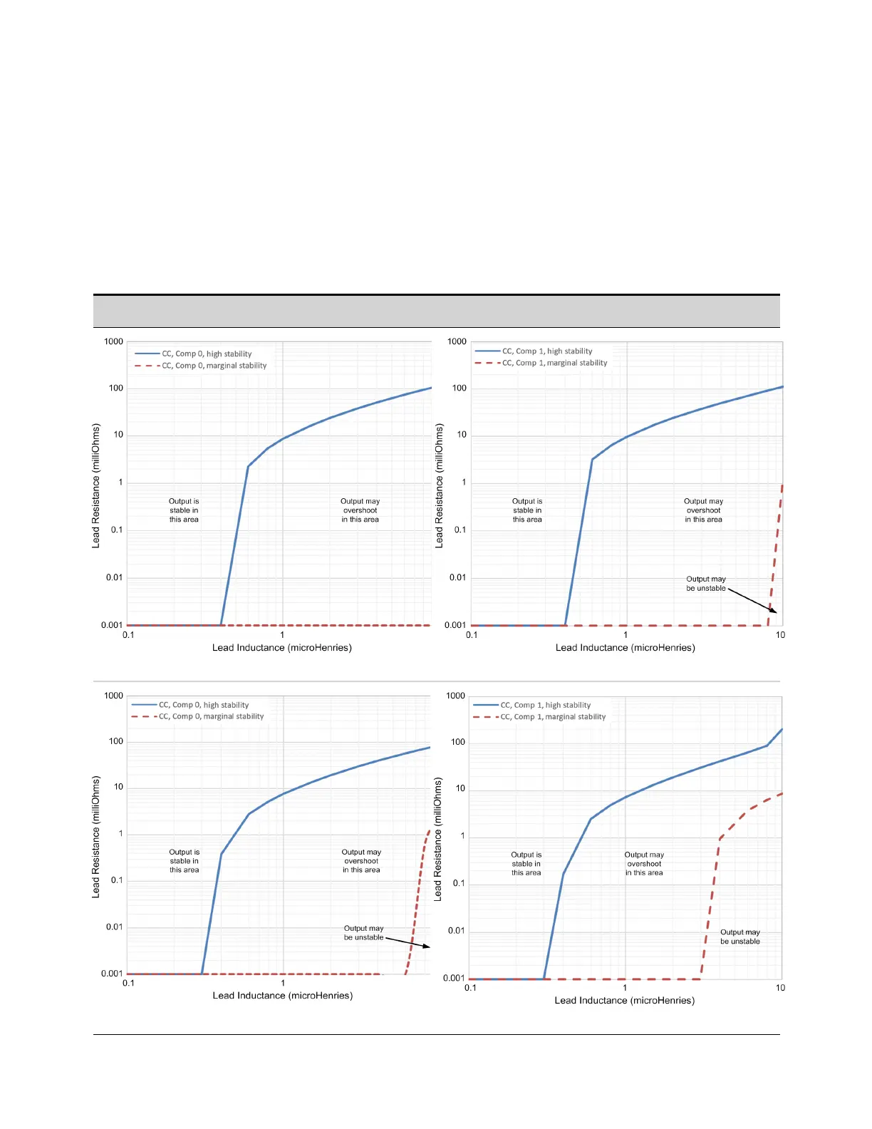
Inductive Load Boundary for Current Priority Mode
The following figures show the boundary limitations for inductive loads with series resistance for
current priority mode. This also applies when operating in CV mode at the current limit setting.
Operation below the marginal stability lines with either Comp 0 or Comp 1 bandwidth settings may
result in output instability. Note that lead and DUT resistance are indistinguishable in this context. It is
also important to consider the voltage drop and power dissipation in the leads from increased lead
resistance. Refer to Inductance Considerations for details. To prevent damage to the unit, refer to
Maximum Load Inductance.
Compensation for Current Priority Mode 0 (20 V units) Compensation for Current Priority Mode 1 (20 V units)
20 V, 5 kW unit 20 V, 5 kW unit
20 V, 10 kW unit
20 V, 10 kW unit
Keysight RP7900 Series Operating and Service Guide 41
1 Quick Reference

 Loading...


