Sense connectors accept wire sizes between AWG 16 (1.5 mm
2
) maximum and AWG 24 (0.2 mm
2
)
minimum. Strip the wire insulation back 10 mm. Tighten the screws securely.
Connect the sense leads as close to the load as possible. Do NOT bundle the sense wire-pair together
with the load leads; keep the load wires and sense wires separate. Sense wiring can be of a lighter
gauge than the load wiring. The sense leads can carry up to 1 mA of current without degrading the
current measurement.
Keep the sense lead resistance less than about 0.5 Ω per lead (this requires 20 AWG or
heavier for a 50 foot length).
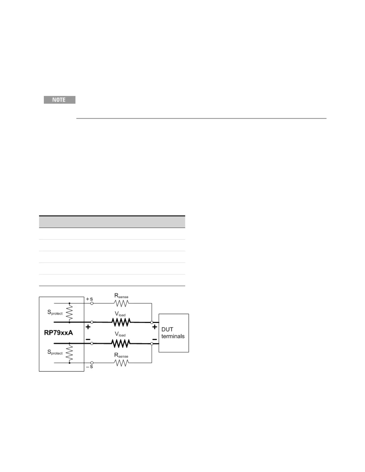
Note however, that any voltage drop in the sense leads can degrade the output voltage regulation. As
the voltage drop in the load leads increases, the load voltage regulation error due to sense-lead
resistance increases according to the following formula:
ΔV
regulation
= 2(V
load
(R
sense
/S
protect
))
R
sense
is the resistance in ohms of each sense lead. V
load
is the voltage drop in each load lead. S
protect
is the internal sense protect resistor (see table).
The formula assumes that the voltage drop in the + and - sense leads and in the + and - load leads are
equal.
Model S
protect
resistor
RP7931A, RP7941A, RP7933A, RP7943A 1.96 kΩ
RP7932A, RP7942A, RP7935A, RP7945A 524 Ω
RP7936A, RP7946A 524 Ω
RP7951A, RP7952A, RP7961A, RP7962A 1.6 kΩ
RP7953A, RP7963A 1.5 kΩ
If the remote sense wires open during normal operation (with output current present), the change in
output voltage at the load will depend on the load current and the wire resistances involved. When
the sense leads open, the unit automatically reverts to local sensing. The voltage at the previous
remote sense point (usually at the load) will drop by an amount given by the following equation:
Δ V= I
out
x (total resistance of load wiring)
Keysight RP7900 Series Operating and Service Guide 73
2 Installing the Instrument

 Loading...


