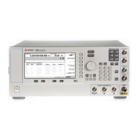
E8257D/67D, E8663D PSG Signal Generators Service Guide
Troubleshooting
Overall Description
1-83
Overall Description
The overall description provides a functional overview of the Agilent PSG signal generators. Some of the functional
blocks discussed are common to many types of instruments, while others are more specific to analog and vector signal
generators.
Common functions:
• A18 CPU
• A19 Power Supply
• Input/Output Interface
Specific signal generator functions:
• Frequency Generation
• Output Power Level/Automatic Leveling Control
• Analog Modulation (Option UNU Standard Pulse, UNW Fast Pulse, UNT AM/FM and Phase Modulation) and Digital
Modulation
A18 CPU
The A18 CPU controls all activities in the signal generator:
• translating information entered from the front panel keys, LAN, GPIB, or Auxiliary Interface (RS–232) into
machine–level instructions
• communicating translated instructions on the internal buses
• monitoring critical circuits for problems, such as unleveled and unlocked conditions
• reporting (on the front panel display) any problems with critical circuits
A19 Power Supply
NOTE The power supply has an internal line fuse that cannot be replaced. If the fuse opens, the power supply must
be replaced.
Voltages
The main power supply converts line voltage (120 Vac or 240 Vac) to regulated dc voltages. Some of the required dc
voltages are not directly available from the main power supply and are provided by re–regulating one of the main
power supply voltages to the required voltage. This regulation can take place on any assembly and then routed to the
required assemblies.
Line Module
The line voltage connects to the power supply through the A22 Line Module. Because the power supply automatically
detects and adjusts to different line voltages, manual line voltage selection is neither necessary nor available.
Power Supply Thermal Sensors and fans
Two thermal sensors prevent the signal generator from overheating. One sensor is internal to the A19 Power Supply;
the other sensor is on the A8 Output. If the signal generator goes into thermal shutdown, the amber and green LEDs
on the front panel blink on and off.
There are two fans in the instrument. One fan cools the power supply. The other is a variable speed fan that increases
and decreases its speed to regulate the instrument’s internal temperature. For reliability, it is important to operate the
instrument with the covers installed to ensure proper airflow and cooling.
Input/Output Interface
Front Panel
The signal generator accepts inputs through the front panel hardkeys and the display softkeys, and provides outputs
on the front panel display, and through the RF output connector. Depending on the model, features, and options, the

 Loading...