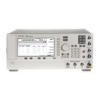
E8257D/67D, E8663D PSG Signal Generators Service Guide
Troubleshooting
Troubleshooting Assembly–Level Problems
1-10
Troubleshooting Assembly–Level Problems
This section provides the following:
• “Front–Panel Display Assembly Troubleshooting” on page 1- 10
• “Power Supply Troubleshooting” on page 1- 14
• “Option 008/009 Troubleshooting” on page 1- 28
• “Self–Tests 1xx for the A13 I/Q Multiplexer” on page 1- 29
• “Self–Tests 2xx: A5 Sampler Self–Test Errors” on page 1- 31
• “Self–Tests 3xx: A7 Reference (Standard) Self–Test Errors (For instruments with serial prefixes < US4805/MY4805)”
on page 1- 33
• “Self–Tests 4xx: A8 Output Self–Test Errors (E8267D only)” on page 1- 34
• “Self–Tests 6xx: A9 YIG Driver Self–Test Errors” on page 1- 37
• “Self–Tests 7xx: A6 Frac–N Self–Test Errors” on page 1- 39
• “Self–Tests 9xx: A10 ALC Self–Test Errors” on page 1- 42
• “Self–Tests 10xx: A7 Reference (Option UNR/UNX and Instruments with Serial Prefixes >= US4805/MY4805)
Self–Test Errors” on page 1- 44
• “Self–Tests 11xx: A18 CPU Self–Test Errors” on page 1- 45
• “Self–Tests 12xx: A26 MID Self–Test Errors (E8257D)” on page 1- 46
• “Self–Tests 12xx: A26 MID Self–Test Errors (E8267D)” on page 1- 50
• “Self–Tests 13xx: A11 Analog/Pulse Modulation Generator Self–Test Errors” on page 1- 54
• “Self–Tests 16xx for the A14 Baseband Generator (Option 601/602)” on page 1- 56
• “Self–Tests 22xx: A8 Output Self–Test Errors” on page 1- 58
• “Self–Tests 24xx: A38 Lowband Filter Self–Test Errors” on page 1- 59
• “Self–Tests 25xx: A43 Amp Filter Self–Test Errors” on page 1- 60
• “Self–Tests 26xx: A8 Output Self–Test Errors” on page 1- 62
Front–Panel Display Assembly Troubleshooting
Overview
The Front–Panel Display Assembly comprises the following:
• a 640 x 320 pixels liquid crystal display (LCD)
• a power switch/flat panel interface board, which contains the power on/off switch, standby LED, and power–on
LED
This board contains the circuitry to disable the power supply. The ON_OFF control line is pulled to a TTL low to
disable the power supply.
Another function of the power switch/flat panel interface board is to route the 8 data bits from the A18 CPU to
the A2 Display.
• a front panel board that contains the front–panel hardkeys, softkeys, and RPG
• a dc to ac inverter, which turns the LCD on and off via control lines received from the CPU
The inverter also converts the 5.2 Vdc to approximately a 160 Vrms, 40 kHz signal to drive the LCD.
Display Controls
Contrast
There are two contrast hardkeys below the A2 Display. The left up arrow key increases the contrast while the right
down arrow key decreases the contrast.

 Loading...