E8257D/67D, E8663D PSG Signal Generators Service Guide
Troubleshooting
Troubleshooting Assembly–Level Problems
1-60
2400 Power Supply Test
• If the +15V and –15V power supplies are good in the above table, replace the A38 Lowband Filter.
2401 RF Path Test
1. Remove the A38 Lowband Filter and insert a semi–rigid extender cable into J3.
2. Connect the extender cable to a spectrum analyzer.
3. Tune the spectrum analyzer and signal generator to 2 GHz. Turn on the signal generator’s RF.
4. You should see a high power signal (>+20 dBm) at 2 GHz on the spectrum analyzer.
• If the signal is good, replace the A38 Lowband Filter.
• If the signal is troubleshoot the RF path.
2402 Lowband Amp/Filter Power Supply
• Replace the A38 Lowband Filter.
2403 RF Path
• Replace the A38 Lowband Filter.
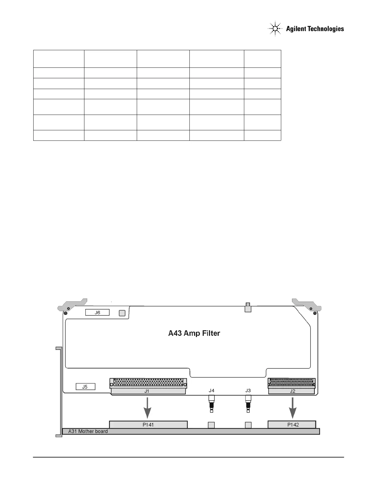
Self–Tests 25xx: A43 Amp Filter Self–Test Errors
+5.2 P142–2, 27 +5.04 +5.36 Main Supply
–5.2 P142–1, 26 –5.30 –5.10 YIG Driver
+5.2 Digital High P141–64, 65, 129, 130 +5.04 +5.36 Main Supply
+3.4 Digital Low P141–60, 61, 62, 63,
125, 126, 127, 128
+3.3 +3.5 Main Supply
+2.6 P141–57, 58, 59, 123,
124
+2.52 +2.68 Main Supply
+1.8 P141–55, 56, 120, 121 –1.75 –1.85 Motherboard
Supply Voltage
(Vdc)
Connector Pins Minimum Value
(Vdc)
Maximum Value
(Vdc)
Origin