Making Measurements 2
Frequency Test Mode
U1271A/U1272A User’s Guide 103
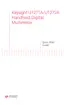
Figure 2-38 Frequency display
The frequency of the input signal is shown in the primary
display. The voltage or ampere value of the signal is shown
in the secondary display. The bar graph does not indicate
frequency but indicates the voltage or ampere value of the
input signal.
Observe the following measurement techniques:
• If a reading shows as 0 Hz or is unstable, the input signal
may be below or near the trigger level. You can usually
correct these problems by manually selecting a lower
input range, which increases the sensitivity of the
multimeter.
• If a reading seems to be a multiple of what you expect,
the input signal may be distorted. Distortion can cause
multiple triggerings of the frequency counter. Selecting a
higher voltage range might solve this problem by
decreasing the sensitivity of the multimeter. In general,
the lowest frequency displayed is the correct one.
Press to cycle through the frequency, pulse width, and
duty cycle measurements.
Press for more than 1 second to exit the frequency
measurement function.