Performance Verification for Analog Generator 2
Keysight U8903B Service Guide 27
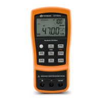
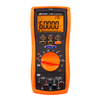
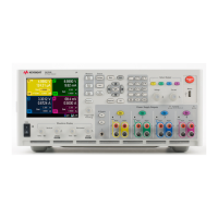
Figure 2-2 U8903B to digital multimeter connections for sine wave amplitude accuracy and flatness
verification
2 Configure the digital multimeter as follows:
– Measurement function: AC voltage
– Level filter: Enabled
–NPLC: 10
– Number readings: 1 (with auto sample event)
– Trigger arming: Hold (suspend)
– Trigger mode: Auto
– ACV mode: Synchronous sub-sampled
– Range: Refer to “Test record for sine wave amplitude accuracy verification” on
page 100
3 Configure the U8903B generator output channels to be tested as follows:
– Connection type: Unbalanced
– Output impedance: 600 Ω
– Output grounding configuration: Floating ground
– Waveform: Sine
– Output state: ON
4 Set both the U8903B output channel 1 and channel 2 to be tested to output a
frequency of 1000 Hz.
5 Set both the U8903B output channel 1 and channel 2 to be tested to output an
amplitude of V
DUT
as given in the “Test record for sine wave amplitude accuracy
verification” on page 100.
6 Set both the digital multimeters’ range as given in the “Test record for sine wave
amplitude accuracy verification” on page 100.
7 Enable the U8903B output channels.
Unbalanced output
channel 1
U8903B audio
analyzer
Digital multimeter 1
Digital multimeter 2
Unbalanced output
channel 2

 Loading...


