K-2April 2003 76-100016-002
PEGAsys™ LV
For replacement, follow the instructions in the ASM Instal-
lation Data Sheet.
K-6 PARTS LIST
The following parts are required for installation and opera-
tion. All are supplied with the ASM.
• Addressable Signal/Sounder Module:
P/N 70-200200-001
• Front Cover Plate:
P/N 06235714-001
• End-of-Line (EOL) Resistor, 4.7 K Ohms, 1/2 W:
P/N 06-250166-452
• End-of-Line (EOL) Resistor, 47 K Ohms, 1/2 W:
P/N 06-250166-596
• Installation Data Sheet: P/N 06-235717-001
K-7 INSTALLATION
Refer to Figure K-2 and to the ASM Installation Instruction
Data Sheet.
K-7.1
Installation Notes
The ASM single printed circuit board is intended for indoor
use and can be mounted in a North American 4-11/16"
electrical box, or 4-inch square 2-1/8-inch deep box. The
module terminal block will accept #12, #14, #16 and #18
AWG wire (4.0 mm
2
, 2.5 mm
2
, 1.5 mm
2
and
1.0 mm
2
re-
spectively). Size #18 AWG is the minimum requirement.
The use of solid wire and an extension ring is recom-
mended.
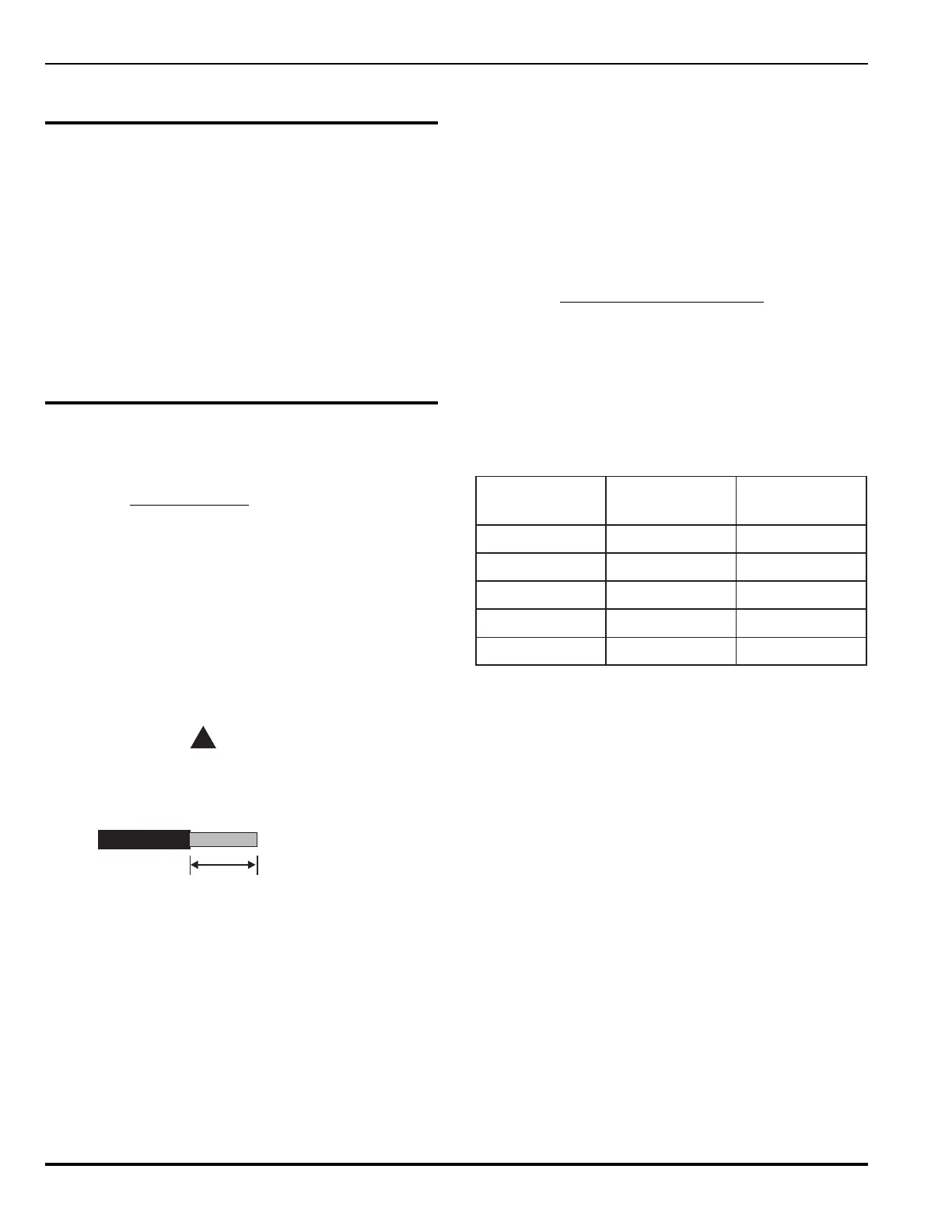
Strip ¼-inch from the ends of all wires that connect to the
terminal block of the module.
CAUTION
!
Exposing more than ¼-inch of wire may cause
a ground fault. Exposing less than ¼-inch of
wire may result in a faulty connection.
1/4“ (6.4mm) NTS
Figure K-2. ¼-Inch Strip
Refer to the National Electrical Code for proper box speci-
fications. ASM volume is 8.94 cubic-inches.
Refer to the RX/TX specifications in the chapters on Op-
eration and Functional Description for addressable-loop
wiring specifications.
Power/Communication (PC) line wiring is power limited and
supervised. For power-limited circuits, use Type FPL, FPLR
or FPLP cable per Article 760 of the National Electrical
Code (NEC).
The note located on the module's product label (ALL OTH-
ERS-POWER LIMITED) must be removed if the module
is connected to a non-power limited supply source.
If the auxiliary notification appliance power source is not
power limited, the output circuit, auxiliary input circuit and
the trouble circuit are non-power limited. Otherwise, all
three circuits are power limited.
Supervision of audio to ASM must be provided by the au-
dio equipment. Power limited or non-power limited ampli-
fier outputs are available.
K-7.2
Output Circuit Characteristics
Output Circuit Rating
2.0 A max. @ 30.0 Vdc
20.0 W @ 70.7 V RMS
20.0 W @ 25.0 V RMS
Maximum Line Resistances
(with 12 AWG wire)
daoL
)spma(
ecnatsiseR
)smho(
htgneL
*)teef(
22.00.02k0.21
55.00.8k0.5
00.10.4k5.2
05.17.2k6.0
00.20.2k2.1
*Note: Consider total line lengths from module to field and
return.