PEGAsys™ LV
April 200376-100016-002
2-1
CHAPTER 2
OPERATION
2-1 INTRODUCTION
This chapter describes the PEGAsys™ LV system con-
trols and indicators located on the display panel. It also
describes the operating procedures and menu system.
2-1.1 Modes of Operation
There are two modes of PEGAsys LV system operation:
1. In the default operation, the panel will be set to latch
all alarm inputs on the system. The latching operation
will not allow the loop input devices to generate an
"trouble off" signal that would possibly interrupt a dis-
charge time delay sequence. To return the panel to
normal, the "RESET" button will need to be pushed.
2. The second mode of operation is non-latching. This
option can be enabled using the PEGAsys Configura-
tion Software (PCS) to define if a loop device input is
to be non-latching. The non-latching operation will al-
low the loop input devices to generate an "alarm off"
signal to the panel. When this signal is received, the
panel would interrupt the discharge time delay se-
quence of operation. However, all outputs that had
been activated previous to the "trouble off" signal will
remain on and latched until the panel is reset.
The advantage of offering latching or non-latching op-
eration per loop input device is that it allows the in-
staller/designer to customize the system. This allows
the intermixing of latching and non-latching devices to
protect critical areas where both types may be speci-
fied.
When an alarm returns to a normal state (trouble off), the
buzzer will sound in a pulsed fashion. The "trouble off"
condition must be acknowledged to silence the buzzer. Dur-
ing the "trouble off" condition, the audible device provides
no sound. The following summarizes the buzzer opera-
tion:
• Alarm condition is indicated by a continuous ON
signal,
• Alarm OFF is indicated by a ½-second ON ½-second
OFF signal, and
• Trouble condition is indicated by a 1 second ON, and
1 second OFF continuous beeping.
Every individual change of status must be individually ac-
knowledged by pressing the <ACKLDGE> (acknowledge)
button to silence the Audible device.
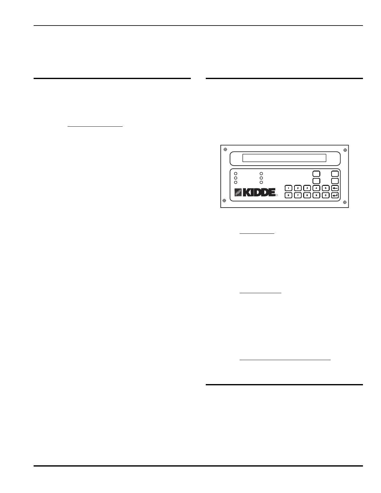
2-2 CONTROLS AND INDICATORS
The control and indicators of the PEGAsys LV system are
located on the display panel, shown in Figure 2-1. The dis-
play panel is mounted on top of the CCM. To gain access
to the CCM, the panel door must be open. Table 2-1 lists
controls and indicators for the display unit, listing name
and functional description.
PRE-ALARM
ALARM
AC POWER
SYSTEM TROUBLE
SUPERVISORY
SILENCE
SYSTEM
ACKNOWLEDGE
SYSTEM
RESET
SILENCE
SCROLL
SYSTEM STATUS DISPLAY
R
Figure 2-1. System Front Panel
2-2.1 LCD Display
The display panel contains an 80-character (2 x 40) alpha-
numeric display. This LCD display is used to present sys-
tem status. In the procedure section of this chapter there
are several simulated LCD display readouts. The LCD dis-
play readouts will be used to aid users in the operation of
the system.
2-2.2 Audible Device
The Display Panel also contains an audible device which
generates two separate audible tones: one for alarms and
one for troubles. This device sounds continuously when a
new alarm condition is received until the condition is ac-
knowledged. It also sounds intermittently when a trouble,
supervisory or pre-alarm condition is received until the con-
dition is acknowledged.
2-2.3 Control and Indicator Description
Refer to Table 2-1 for complete description of controls and
indicators.
2-3 SYSTEM SECURITY
The PEGAsys LV system provides three distinct levels of
program protection, as required by UL Standard 864. The
user can only access the system by entering a valid pass-
word. Typical valid passwords consist of three or four char-
acters, but may be up to eight characters in length.