April 200376-100016-002
PEGAsys™ LV
7-1
CHAPTER 7
INSTALLATION
7-1 INTRODUCTION
This chapter provides information necessary to install the
PEGAsys™ LV system. Installation consists of installing a
complete system. The procedures in this chapter should
be accomplished by technicians familiar with fire alarm sys-
tem installation and the requirements of relevant NFPA
regulations.
7-2 MATERIALS REQUIRED FOR
INSTALLATION
The materials listed below are not supplied with the sys-
tem, but are required for installation:
• No. 10 or ¼-inch Mounting Hardware
• Electrical Conduit for AC Input Power
• 4-inch Electrical Junction Boxes (as required)
• Wire-Nuts and Crimp-On Terminals (as required)
• Ground Strap (for handling printed circuit boards)
7-3 INSTALLATION PROCEDURE FOR
CENTRAL CONTROL PANEL
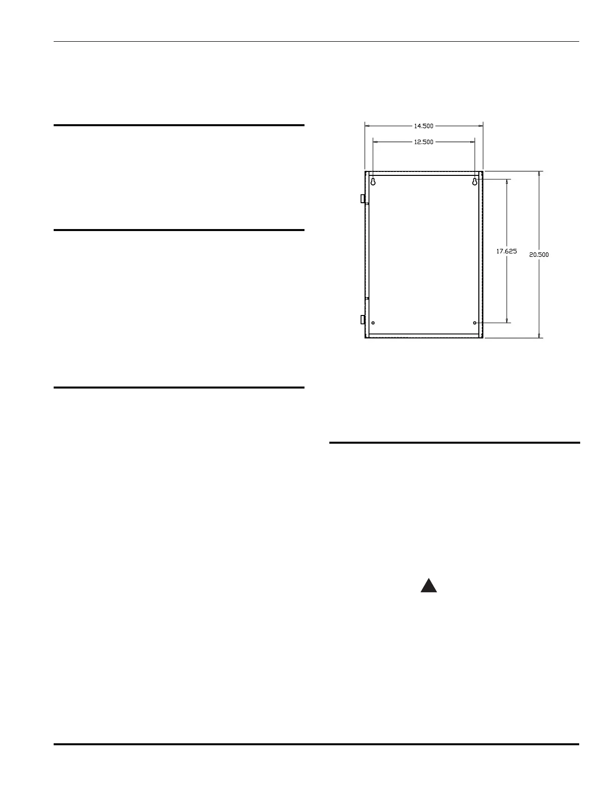
The PEGAsys LV Central Control Panel enclosure is 20.5
inches high x 14.5 inches wide x 5½ inches deep. It is
designed to be surface or semi-flush mounted using No.
10 or ¼-inch hardware. The type of hardware to be used is
at the discretion of the installer, but must be in accordance
with good electrical and safety practices.
Figure 7-1 shows the hole layout of the enclosure's mount-
ing area.
To facilitate mounting the enclosure to its wall position, re-
move the enclosure’s front door. Disconnect the ground
wire before removing the door.
To remove the front door, open the door approximately
90º from its closed position and lift it up enough to allow
the door’s hinge pins to clear their mating hinge sockets
located on the left side of the Central Control Panel.
Place the mounting screws into the top two holes in the
wall. Leave approximately ¼-inch of both screws exposed.
Carefully place the two key holes over the screws in the
wall. Ensure the enclosure has its door hinge sockets lo-
cated to the left as you face the enclosure. Allow the en-
closure to gently come to rest on the screws. Tighten the
screws.
Figure 7-1. CCP Installation Drawing
With the enclosure held by the top two screws, place the
bottom two mounting screws in place. Tighten the screws.
Reinstall the enclosure door at this time. Care must be
taken when installing the door to ensure that the hinge
pins are lined up correctly.
7-4 CONNECTING AC POWER
AC power must be provided to the Central Control Panel’s
internal power supply using three conductors. The AC
power cable is to be run through a conduit from a dedi-
cated, 15 Amp circuit breaker. The conduit must be at-
tached to the right side of the Central Control Panel
enclosure through one of the knockouts near the upper
right corner of the enclosure.
See Appendix A for AC branch circuit requirement details.
High voltages may be present when
connecting AC power to the Central Control
Panel. Suitable precautions must be taken to
avoid injury.
Note: All Non-Power-Limited wiring must be routed away
from Power Limited wiring by a minimum of ¼-
inch, per NFPA and UL requirements. For Power
Limited Circuits use Type FPL, FPLP or FPLR
cable per NEC Article 760.