April 2003 76-100016-002
PEGAsys™ LV
5-2
CAUTION
!
Some components are subject to damage from
electrostatic discharge (ESD). These
components are not to be removed from their
protective wrappings until they are to be
installed in their respective equipment
locations, and then only by personnel
connected to earth ground.
5-4.1 Required Tools
The following tools will be required to perform the removal
and replacement procedures.
• Small Flat-Blade Screwdriver
• 6" Flat-Blade Screwdriver
• No. 2 Phillips Screwdriver
• Wire Striper
• Small Needle Nose Pliers
• Ground Strap
5-4.2 Central Control Module
The following paragraph provides the step-by-step proce-
dure for replacing the CCM.
1. Ensure all programming is saved using PCS software.
2. Remove all field wiring and internal cables.
3. Remove the six mounting screws while holding the
CCM in place.
4. Remove CCM from cabinet.
5. Remove new CCM from packing and inspect for physi-
cal damage.
6. Install new CCM in the reverse order of the removal
steps (listed above).
5-4.3 RX/TX Module
The following paragraph provides the step-by-step proce-
dure for replacing the RX/TX module.
Ensure that the RX/TX jumpers are set properly during
the procedure. Verify that the settings of the jumpers on
the RX/TX Module conform to the wiring style of the sys-
tem being installed. The RX/TX is shipped from the fac-
tory programmed for Style 6 wiring style. Refer to the
installation drawing 06-235443-002, in Appendix I, which
shows the jumper locations on the RX/TX module. The
settings are used to set the wiring style ( 4, 6 or 7), with 7
being used with loop isolators. Jumpers on the RX/TX Mod-
ule are noted by JP x and Wx (x = a single digit) call-outs on
the module board. Table 5-2 lists the types of allowable con-
figurations you can select along with their respective jump-
ers.
1. Disconnect plug from terminal T1.
2. Remove the two mounting screws from the module
and move module to gain access to connected wiring.
3. Remove the plug from the RS-232 port.
4. Remove power plug from connector jack J1.
5. Remove new RX/TX module from packing and inspect
for physical damage.
6. Ensure jumper configuration is set.
7. Install new RX/TX in the reverse order of the removal
steps (listed above).
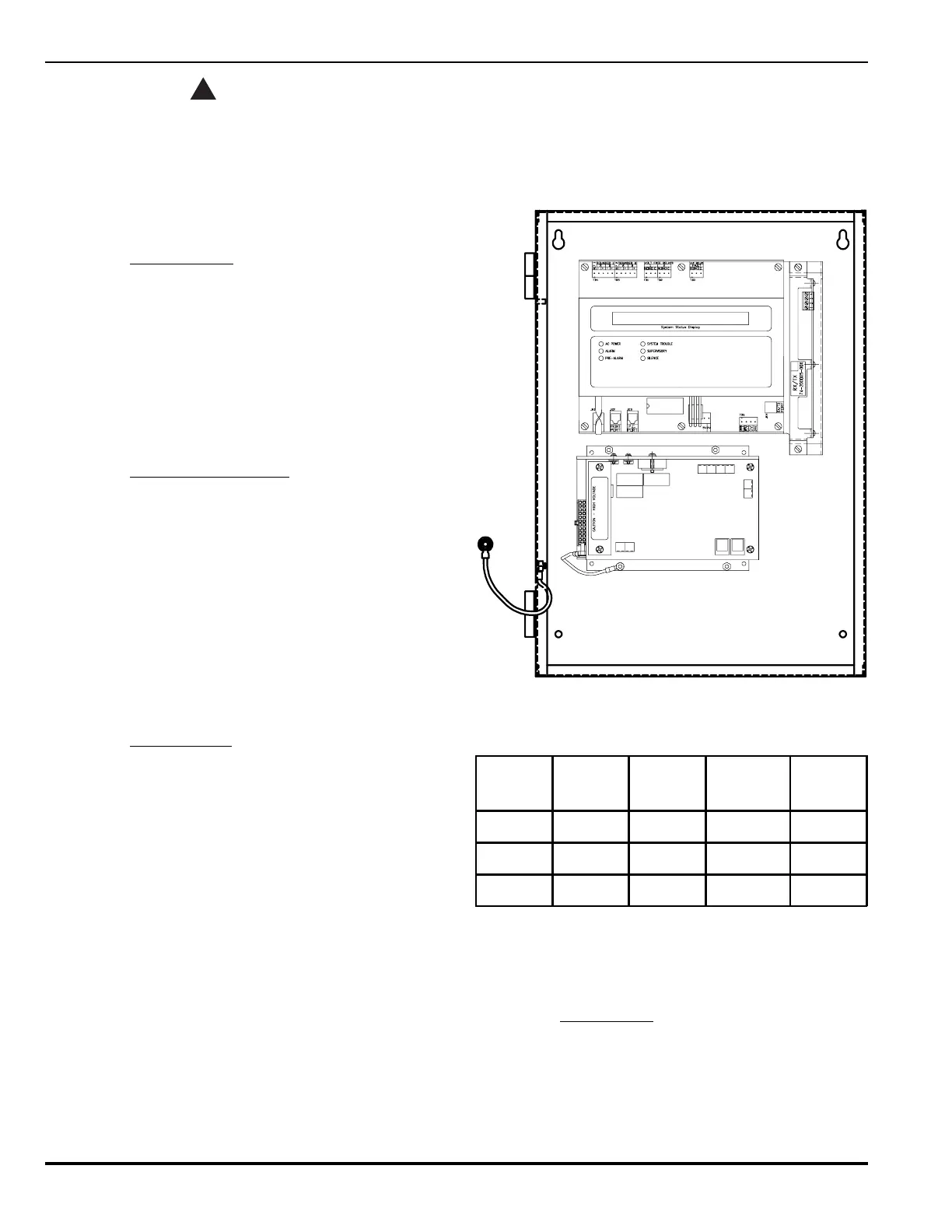
Figure 5-1. PEGAsys LV Module Layout
Table 5-2. RX/TX Configuration Selection
Jumper Style 4 Style 6
Style 6 w/
Loop
Isolator
Style 7
W1 and W2 Open Shorted Shorted Shorted
JP2 Shorted Shorted Open Open
JP3 Shorted Shorted Open Open
Note: Style 7 requires the use of field-installed loop iso-
lators. The RX/TX module requires the use of one
(1) P/N 74-200012-001 isolator module to oper-
ate in the Style 7 configuration.
5-4.4 Field Devices
The following paragraph provides the step-by-step proce-
dure to replace field devices in the PEGAsys LV system.
Note: Smoke and heat detectors can be replaced with-
out powering down the system. When adding new
loop devices to the system, the panel will need to
be powered down.