A-1 April 200376-100016-002
PEGAsys™ LV
APPENDIX A
POWER SUPPLY REQUIREMENTS
A-1 AC BRANCH CIRCUIT
The PEGAsys™ LV Fire Alarm Control Unit requires con-
nection to a separate dedicated AC branch circuit (120 or
240 Vac), which must be labeled FIRE ALARM. This branch
circuit must connect to the line side of the main power feed
of the protected premises. No other equipment may be
powered from the fire-alarm branch circuit. The branch cir-
cuit wire must run continuously, without any disconnect
devices, from the power source to the fire alarm control
panel. Over-current protection for this circuit must comply
with Article 760 of the National Electric Code, NFPA-72, as
well as applicable local codes. Use a minimum of # 14
AWG with 600-V insulation for this branch circuit. (See
Tables A-1 and A-2.)
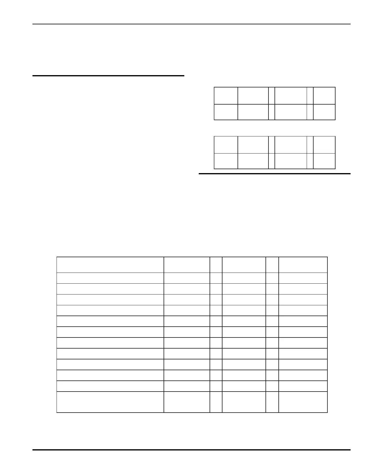
Table A-1. AC Branch Circuit Requirements (120 Vac)
eciveD
epyT
forebmuN
seciveD
tnerruC
)spmA(warD
latoT
tnerruC
lortnoC
lenaP
1X 9.1=9.1
Table A-2. AC Branch Circuit Requirements (220 Vac)
eciveD
epyT
forebmuN
seciveD
tnerruC
)spmA(warD
latoT
tnerruC
lortnoC
lenaP
1X 59.=59.
A-2 SYSTEM STANDBY POWER
REQUIREMENTS
The control panel provides regulated power for operating
external devices, system operation, and standby battery
charging.
Note: Use Table A-3 (standby or non-alarm) to determine
main system power supply and any installed aux-
iliary power module standby current requirements.
Table A-3. Standby Power Requirements (24 Vdc)
eciveD/eludoM
tnerruCybdnatS
)spmA(
metsyS/eludoM
ybdnatSmumixaM
)spmA(tnerruC
eludoMlortnoClartneC070.0X1= 070.0
eludomXTXR530.0X =
rotinoMylppusrewoP060.0X =
)2dna1setoNeeS(A5.1xaM,1tuptuOyrailixuA X=
)2dna1setoNeeS(A5.1xaM,2tuptuOyrailixuA X=
SECIVEDDLEIF
rotceteDnoitazinoI004000.0X =
rotceteDcirtceleotohP504000.0X =
tupnItcatnoCelbasserddA013000.0X =
tuptuOtcatnoCelbasserddA033000.0X =
srotalosIpooL100.0X =
rofnmuloCmuS
daoLybdnatS
)2setoN(
=spmA
Notes:
1. Auxiliary Outputs must be considered for total standby alarm loading of the system power supply.
2. Use of auxiliary 24 Vdc outputs of during standby operation must not cause the calculated standby current of the
system to exceed its rated maximum as defined in the Table A-6.