A-2April 2003 76-100016-002
PEGAsys™ LV
A-3 SYSTEM ALARM POWER REQUIREMENTS
Note: Use Table A-4 (Alarm ) to determine alarm current requirements for main system power supply.
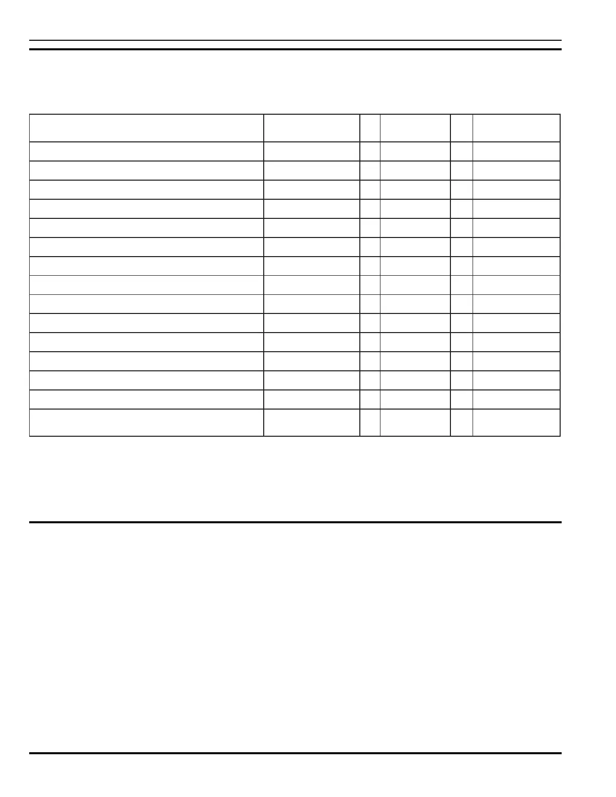
Table A-4. Alarm Power Requirements (24 Vdc)
eciveD/eludoM )spmA(tnerruCmralAmetsyS/eludoM
mralAmumixaM
)spmA(tnerruC
eludoMlortnoClartneC 012.0X1=012.0
)1etoNeeS(tuptuO20PMdna10PMMCC X
eludoMXTXR 530.0X =
rotinoMylppuSrewoP 060.0X =
)2etoNeeS(A5.1xaM,1tuptuOyrailixuA X=
)2etoNeeS(A5.1xaM,2tuptuOyrailixuA X=
SECIVEDDLEIF
rotceteDnoitazinoI 044000.0X =
rotceteDcirtceleotohP 544000.0X =
tupnItcatnoCelbasserddA 083000.0X =
rotinoMenoZelbasserddA 004000.0X =
tuptuOtcatnoCelbasserddA 053000.0X =
)evitcA(srotalosIpooL 700.0X =
OhtiwesurofMLAPNOIRDSSHTX050.0X =
rofnmuloCmuS
daoLmralA
=spmA
1. CCM Alarm condition power requirements must be evaluated for loading of the signaling devices. Each signal circuit
can provide up to 2 Amps of 24 Vdc power for signaling device use.
2. Auxiliary Outputs would have to be considered for total alarm loading of the system power supply.
3. With constant power solenoid, the current draw of the solenoid must be added in the calculation. Momentary
solenoid is negligible in its current draw and should not be added into the calculation.
A-4 CALCULATING BATTERY SIZE REQUIRED
Table A-5 sums the standby and alarm loads to arrive at the battery size, in amp hours (AH), needed to support the control
panel. There is a maximum battery size which the system power supply (P/N 76-100009-010) is capable of charging. Select
batteries which meet or exceed the total amp hours (AH) calculated and are within the acceptable range of the system
battery charger output, which is 12 to 99 AH. Using the totals from Table A-3 and Table A-4, complete Table A-5 to determine
the total battery (AH) capacity necessary for the power supply.