April 2003 76-100016-002
PEGAsys™ LV
7-4
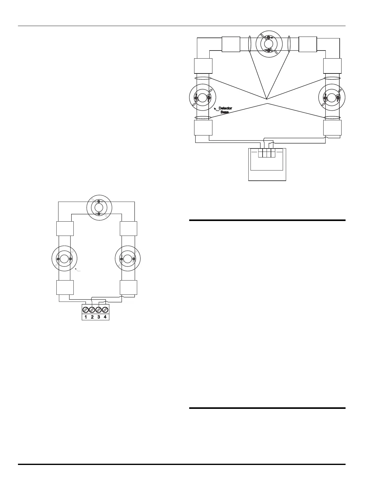
Loop Isolator devices are available to support NFPA-72
Wiring Style 7 and are installed on the PC line of the RX/
TX module. Isolator packages are available for electrical
box mount (Single Gang), 6-inch base mount and an RX/
TX mount.
By "flanking" each group of loop devices with a pair of loop
isolators, each zone is protected from opens and shorts. A
zone is defined as a group of loop devices. In this style of
installation, a short circuit between any two loop isolators
will not affect any other zone. The isolators on each side
of the short will open the PC line.
Figure 7-17 and the RX/TX Module Installation Wiring Dia-
gram (see Appendix I) depict a typical NFPA Style 7 instal-
lation.
Note: The maximum number of loop devices that can
be connected between loop isolators is thirty (30).
During a short circuit fault condition, the control
panel will register a trouble condition for each de-
vice located between the two affected loop isola-
tors.
Loop
Isolator
Zone 1
Zone 2
Zone 3
Loop
Isolator
Loop
Isolator
Loop
Isolator
Note: Each zone can consist of 30 loop devices
between loop isolators.
Detector
Base
TB1 of
RX/TX Module
Figure 7-7. Style 6, RX/TX PC Line Connections with
Loop Isolators
Note: Adjacent loop isolators must be within
20 ft. of a device with wiring in conduit.
74-200012-001
Mounted to RX/TX
LOOP ISOLATOR
4321
24V
24V
RET
RET
RX/TX
Loop
Isolator
Zone 1
Zone 2
Zone 3
Loop
Isolator
Loop
Isolator
Loop
Isolator
See Note
Loop
Isolator
Loop
Isolator
Figure 7-8. Style 7, RX/TX PC Line Connection
7-7 OUTPUT SIGNAL CONNECTION
The PEGAsys LV System provides output signals to drive
alarm devices and communicate with central stations and
control equipment. These outputs are provided on the CCM
and optional RX/TX Control and Signaling Modules.
All field wiring to output devices is to be run from the out-
put device circuit to the field devices. The wiring must be
brought through any convenient Central Control Panel
enclosure knockout. Route the wiring to the terminal block
located on the Central Control Module, insert the end of
each wire into its proper terminal block slot, and tighten
the slot screws firmly.
Instructions for connecting output devices are provided on
their respective installation wiring diagrams located in the
Appendix I of this manual. Refer to the respective
manufacturer’s literature for specific installation instruc-
tions of output devices.
Note: All Non-Power Limited wiring must be routed away
from Power Limited wiring by a minimum of ¼-
inch, per NFPA and UL requirements. For Power
Limited Circuits use Type FPL, FPLP or FPLR
cable per NEC Article 760.
7-8 EXTERNAL POWER FAILURE INDICATOR
CONNECTION
The PEGAsys LV System provides a 2 A @ 30 Vdc SPDT
relay on the power supply monitor module that de-ener-
gizes (normally powered) in the event of a power supply
trouble. Troubles include:
 Loading...