April 200376-100016-002
PEGAsys™ LV
7-3
nection cable wire into its proper TB1 slot. Tighten the slot
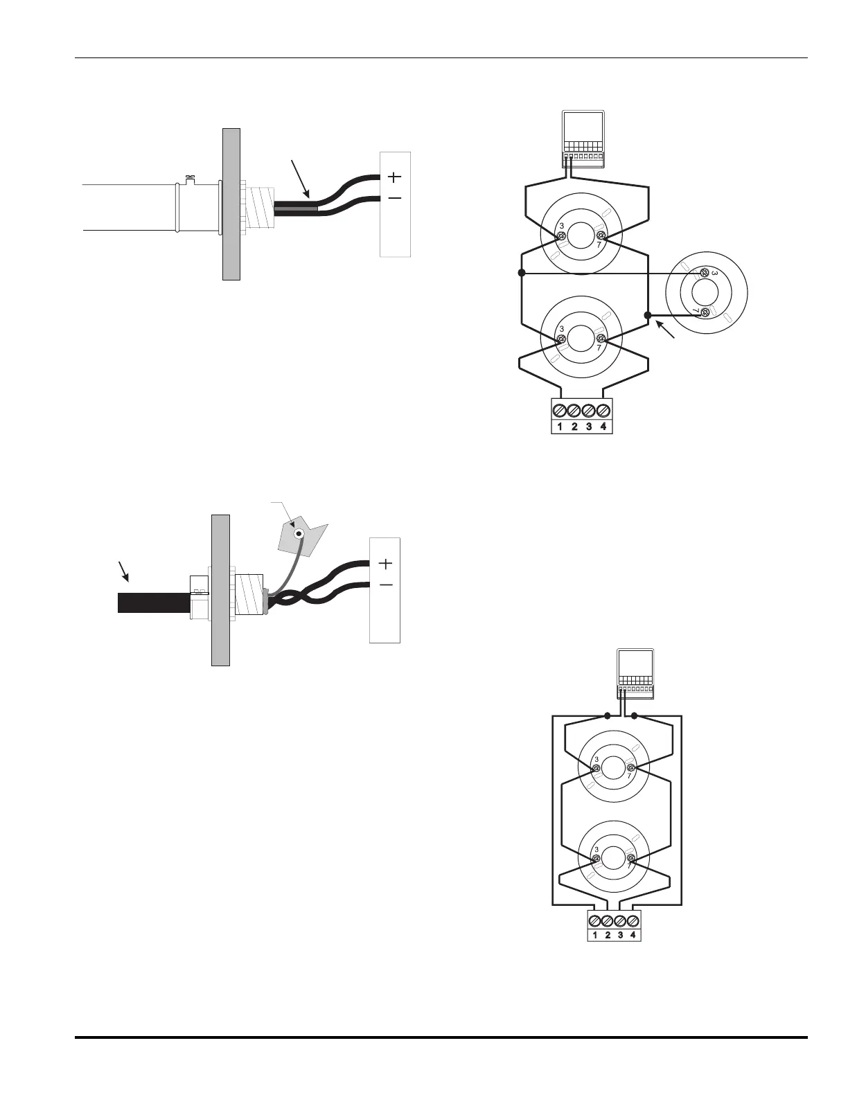
screws firmly. See Figure 7-3 for a conduit to CCP ex-
ample. See Appendix B for recommended wiring.
Twisted, Unshielded
Wire
TB1
Enclosure
RX/TX
Module
Figure 7-3. Conduit to CCP
In retrofit applications where existing wiring will be used,
do not exceed the SLC resistance and capacitance limita-
tions listed above. All conduit and conductors must meet
NEC, NFPA-72 and any applicable local code requirements.
See Figure 7-4 for existing shielded cable termination. Op-
tionally, the PC line can be installed in a separate conduit
as shown previously, thus allowing the PC line to use
twisted, unshielded wire.
Grounding
Nut
Shielded
Wire
Enclosure
RX/TX
Module
TB1
Figure 7-4. Shielded Wire to CCP
Note: All new RCUs are shipped from Kidde with their
address set to 000. This address is reserved for
unregistered devices and cannot be used as a reg-
istered address. The unaddressed devices must
be connected to the RX/TX Module one at a time
in order to address them. Otherwise devices may
be pre-addressed or multiple pre-addressed loop
devices may be connected to the RX/TX PC line
at the same time using the hand-held device pro-
grammer (P/N 74-200013-001) .
Refer to Table 5-2 for a list of the types of allowable con-
figurations that can be selected, along with the respective
jumper settings for those configurations. As described in
this chapter, the PC line can be configured in Style 4, 6
or 7. Each Style is represented in Figures 7-5 through 7-8.
Style 4 configurations allow T-tapping. T-tapping is only
limited by sound installation techniques.
MODEL AI, N/O
INSTRUCTIONS
SEE INSTALLATION
CAT. NO. 70-407008-001
SmartOne
TM
FOR SERVICE SEND TO:
KIDDE-FENWAL, INC.
400 MAIN ST.
ASHLAND, MA 01721
DATE OF MANUFACTURE:
MAX. INSTALL. TEMP. 120°F
7654321
06-235578-001
PC PC PC PC
(+) (-) (+) (-)
8
A
SW
B
SW
(+)
LED
(-)
LED
ALLTERMINALS ARE POWER LIMITED
Addressable
Contact Input
Device
Detector Bases
T-Tap
TB1 of
RX/TX Module
Figure 7-5. Style 4, RX/TX PC Line Connections
In the Style 6 wiring configurations, the RX/TX automati-
cally transmits data and power bi-directionally when a break
in the PC line wiring occurs. If the break is in a single con-
ductor, all loop devices will remain fully operational. For
Style 6 PC line connections, if a PC line open trouble is
encountered, use the system reset switch on the display
and control board to reset the PC line to normal once the
fault is corrected.
MODEL AI, N/O
INSTRUCTIONS
SEE INSTALLATION
CAT.NO. 70-407008-001
SmartOne
TM
FOR SERVICE SEND TO:
KIDDE-FENWAL, INC.
400 MAIN ST.
ASHLAND, MA 01721
DATE OF MANUFACTURE:
MAX. INSTALL.TEMP. 120°F
7654321
06-235578-001
PC PC PC PC
(+) (-) (+) (-)
8
A
SW
B
SW
(+)
LED
(-)
LED
ALLTERMINALS ARE POWER LIMITED
TB1 of
RX/TX Module
Detector Bases
Addressable
Contact Input
Device
Figure 7-6. Style 6, RX/TX PC Line Connections