1-1 April 2003
PEGAsys™ LV
76-100016-002
CHAPTER 1
GENERAL INFORMATION
1-1 INTRODUCTION
This manual contains the operation, maintenance, trouble-
shooting, parts listing and installation information neces-
sary to support the PEGAsys™ LV Intelligent Fire Alarm
Control Unit.
Note: This manual is to be used by trained distributors
only. The entire manual should be read and fully
understood prior to installation. Refer to Figure
1-1 for the PEGAsys LV overall system diagram.
1-1.1
System Description
PEGAsys LV is a fire alarm and off-premises control sys-
tem which can be used for local signaling and releasing
device service. The system is a microprocessor based de-
sign for use with intelligent detectors and loop devices.
The system utilizes distributed intelligent field devices.
These devices are typically smoke detectors, contact in-
put devices, relay outputs and signal output modules which
represent a single fire alarm initiation/indicating zone. Each
device contains its own data transceiver, micro controller,
4k of memory and applicable algorithms which allows each
device to operate independently of the control system.
These unique devices have the ability to analyze informa-
tion, make decisions and store information within them-
selves. They communicate with the PEGAsys LV unit using
the BIP protocol which utilizes a two-wire (Style 4), four
wire (Style 6) or isolated (Style 7) multiplex trunk. The
PEGAsys LV can support up to 255 device addresses.
The PEGAsys LV is capable of controlling a wide variety of
auxiliary devices, such as relays, audible/visual indicating
signal devices and agent/sprinkler release systems. The
system also supports the use of serial printers which pro-
vide hard copy of system status information.
1-1.2
System Components
The system is comprised of three major components, as
shown in Figure 1-1: the Central Control Panel (CCP) which
communicates with the field devices and drives output
devices such as alarm signals that communicate with cen-
tral stations and various types of control equipment; a dis-
play panel located on the CCP that provides system status
LEDs and Control Switches; and an 80-character LCD that
provides alphanumeric display of system status informa-
tion.
The PEGAsys LV Central Control Unit (P/N 76-100000-
506) consists of the Central Control Module (CCM) as-
sembly, one receiver/transmitter (RX/TX) module and one
power supply assembly.
1-2 COMPONENT DESCRIPTION
The following paragraphs give a brief description of each
component used in the PEGAsys LV system. For func-
tional descriptions of each component, see Chapter 3 of
this manual.
1-2.1
Central Control Module (CCM)
The CCM assembly is the heart of the system and is com-
prised of two (2) printed circuit board (PCB) assemblies,
the display module and the main processor module. The
CCM controls the operation and supervision of all the sys-
tem modules and software within the PEGAsys LV sys-
tem. It receives loop device data from the RX/TX module,
processes the data based on pre-programmed instructions
and transmits output commands to the output circuits, field
devices and display module(s).
1-2.2
Display Module
The display module assembly, attached to the main pro-
cessor PCB, provides the system with the operator inter-
face for control switches, system status LEDs, system
trouble/alarm buzzer, an 80-character (2 x 40) LCD dis-
play and an integral numeric keypad. The keypad is used
for entering the security password and navigating through
the user menus. The system buzzer provides two (2) dis-
tinctly different signaling patterns for audible warning of
system alarms and troubles.
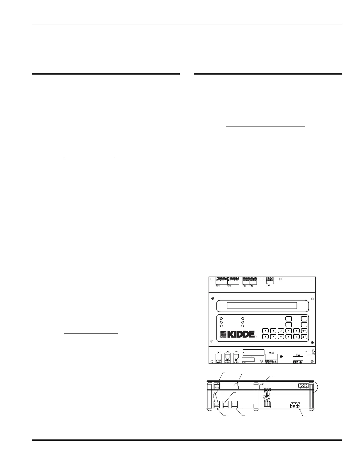
PRE-ALARM
ALARM
AC POWER
SYSTEM TROUBLE
SUPERVISORY
SILENCE
SYSTEM
ACKNOWLEDGE
SYSTEM
RESET
SILENCE
SCROLL
SYSTEM STATUS DISPLAY
R
Display Reset
Switch
PLG2
JK1
JK2
PLG3
SW1
PLG2
JK3
PLG1
PRINT PORT
DS1
0V
24 VDC
EARTH FAULT
SUPPLY FAULT
TB6
BUZZER
Processor
Port
Display
Port
PC Port
Display Trouble
LED
24VDC From
Power Supply
Figure 1-2. Central Control Module (CCM)