April 2003 76-100016-002
PEGAsys™ LV
7-2
Ensure that the circuit breaker at the dedicated AC power
source is in the OFF position. Attach the three AC power
conductors to TB1 on the Central Control Panel’s power
supply PCB, as shown on drawing number 06-235443-003
in Appendix I.
7-5 INSTALL AND CONNECT DC POWER
Space is provided within the Central Control Panel for two
12 V, 12 AH sealed lead-acid batteries used for 24-hour
standby operation.
7-5.1
Battery Enclosure
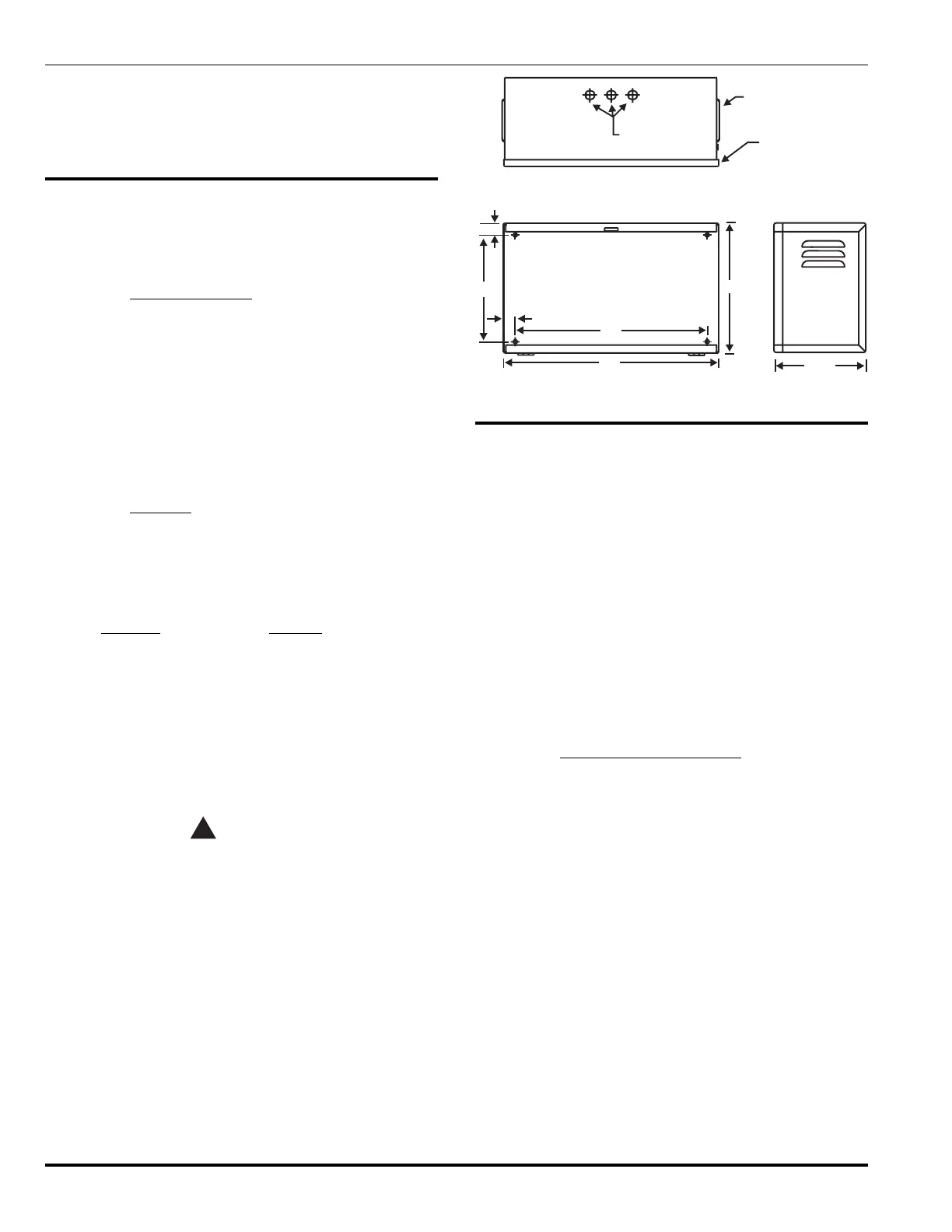
A separate UL Listed battery enclosure, shown in Figure
7-2 (P/N 76-100010-001), is used to house up to two 12 V,
40 AH, sealed lead-acid batteries. The enclosure is de-
signed to be surface mounted using only hardware similar
to that used on the CCP (see Paragraph 7-3) and must be
mounted within 100 feet of the panel.
Note: Wiring for the batteries to the power supply must
be sized accordingly to prevent unacceptable volt-
age drops.
7-5.2 Batteries
Refer to Appendix A for required system power calcula-
tions. Refer to Appendix E for FM Pre-Action/Deluge sprin-
kler requirements for 90-hour standby periods.
Recommended battery models are:
Part No. Battery
06-115915-047 12-AH Battery
06-115915-046 17-AH Battery
89-100052-001 33-AH Battery
The batteries should be rated for standby power use and
fit within the physical dimensions of the respective enclo-
sure. The batteries must have terminals that accept stan-
dard ring-type solderless connectors.
CAUTION
!
Do not connect the batteries to the system
power supply at this time. Connect the
batteries at the end of system installation.
Connection to the power supply must be according to draw-
ing contained in Appendix I.
KNOCKOUTS FOR
.50 CONDUIT
(3 PLACES)
VENT BOTH
SIDES
8.25“
18“
0.94“
20“
12“
10“
0.94“
DOOR
Figure 7-2. Battery Enclosure
7-6 FIELD DEVICE CONNECTION TO RX/TX
MODULE
Field devices connect to terminal block (TB1) located on
the PEGAsys LV System’s Receiver/Transmitter Module
(RX/TX). The cable connecting the field devices to the RX/
TX module provides power and bi-directional communica-
tions to the loop devices. One RX/TX module can support
up to 255 SmartOne
®
addressable field devices. These
255 addresses can be any mixture of intelligent loop de-
vice inputs and outputs without restriction.
Note: All Non-Power Limited wiring must be routed away
from Power Limited wiring by a minimum of ¼-
inch, per NFPA and UL requirements. For Power
Limited Circuits use Type FPL, FPLP or FPLR
cable per NEC Article 760.
7-6.1 Wiring the RX/TX PC Line
The RX/TX PC line uses Broadcast Indexing Protocol (BIP)
for communications with intelligent loop devices. The PC
Line may be configured in NFPA-72 Style 4, 6 or 7. The
PC Line is capable of supporting 255 intelligent loop de-
vices on a 2-wire loop.
In retrofit applications, existing wiring can be used as long
as it meets NEC 760 and NFPA 72 requirements. When
installing new wiring or using existing wiring, it is neces-
sary to check line resistance and capacitance. Total line
resistance cannot be greater than 26 Ohms, and capaci-
tance can not exceed 0.25 microFarad. Kidde recommends
the use of No. 18 AWG minimum, low capacitance, twisted,
unshielded wiring as the connection cable between the
RX/TX Module and the field devices
The PC line to the loop devices can be run in conduit to
the Central Control Panel cabinet. The conduit, if used,
must be attached through any convenient Central Control
Panel enclosure knockout. Route the connection cable to
TB1 on the RX/TX PCB and insert the end of each con-