PEGAsys™ LV
April 2003 76-100016-002
2-10
Table 2-5. Test Menu Functions
WARNING
!
The Alarm Simulation Test must be used with care. When activated, the Alarm Simulation Test (AST)
processes pre-programmed outputs which are related to the activated (simulated) input device. Before
using the AST, ensure that any associated outputs are disconnected or isolated to prevent unexpected
outputs (releases, signals or shutdowns).
1 = Level One, 2 = Level Two, M = Manufacturer Level
noitcnuFnoitpircseDalumroFleveLsseccA
tseTpmaLytilanoitcnufsDELmetsystsetotresuelbanE 1-4M/2/1
tseTeciveDpooL
fopuorgrorotcetedafotsetcinortcelenaetavitcaotresuswollA
srotceted
1-2-4M/2/1
tseTyrettaB yticapacyrettabyfirevottsetyrettabaetavitcaotresuswollA 3-4M/2/1
tseTklaWelbanE tsetklawotsecivedfoegnarayficepsotresuswollA 1-4-4M/2
tseTklaWelbasiDedomtsetklawelbasidotresuswollA 2-4-4M/2
tseTnoitalumiSmralA
otstupnifopihsnoitalerdemmargorpyfirevotrellatsniswollA
evitcaerastuptuogniyfirevdnastupnignitavitcaybstuptuo
5-4M/2
1080 AOF_ _ _ _PHOTOELECTRIC DETECTOR
40_CHARACTER_LOCATION_MESSAGE
Note: If the alarm is a zone alarm, the address “1000”
will be displayed, indicating that active device(s)
in failsoft mode on the indicated SLC have gone
out of alarm.
6. Each device which goes out of alarm must be acknowl-
edged with the <ACKLDGE> button (non-latching).
For latching mode: To return the system to normal,
press the <RESET> button once. If powering a 4-wire
detector from the PEGAsys LV, the <RESET> button
will need to be pushed once to reset the detector and
once to reset the panel to a normal condition.
7. Once all alarms have been cleared in a non-latching
operation, the display will read: NO ACTIVE ALARM
REMAINS. At this time, the system may be reset by
operating the <RESET> button.
8. When the system is properly reset, the display will show
the System Status Normal message, time and date.
The preceding will happen if no active troubles or
supervisories are present, in which case the “Active
Troubles” or “Active Supervisories” message will be
displayed.
2-6.3 Active Supervisory Mode
The system enters supervisory mode when it detects an
abnormal condition on the system that has been defined
to be a higher priority than a common trouble. This type of
supervisory mode is usually assigned by the installer/de-
signer to monitor critical parts of the system.
2-6.3.1 SUPERVISORY MODE INDICATION
The following indicates the system is in the supervisory
mode of operation.
•. The yellow SUPERVISORY LED will be flashing at a
one (1) second rate, and there will be a pulsing buzzer
at the CCM. This audible is distinctively different than
the alarm signal pattern at the CCM.
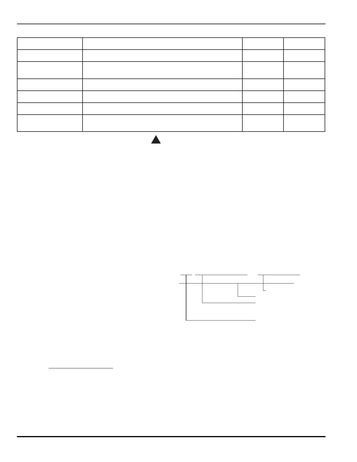
• The 80-character display will cycle between all cur-
rently active supervisory events. See Figure 2-4 for
an example.
1080 SUPERVISORY ON_ _ Contact _ Monitor
___40_Character _ Location _ Message
Device Location (40 Characters)
Device Type
Supervisory On
Device Address
(1001-1255)
Figure 2-4. Supervisory Example for
Supervisory Mode Indication
2-6.3.2 SUPERVISORY MODE USER ACTION
The following steps should be performed when the sys-
tem enters the supervisory mode of operation:
1. To silence the supervisory audible signal, all current
supervisories must be acknowledged by pressing the
<ACKLDGE> button. This will silence the system
buzzer.
2. When all supervisory conditions have been acknowl-
edged, the 80-character display will read: XXX AC-
TIVE SUPERVISORY REMAIN, with XXX representing