April 200376-100016-002
PEGAsys™ LV
3-1
CHAPTER 3
FUNCTIONAL DESCRIPTION
3-1 INTRODUCTION
This chapter provides a functional description of the de-
vices/modules used in the PEGAsys LV system configu-
ration. Each functional description covers one of the blocks
shown in the overall block diagram, Figure 3-1.
3-2 BLOCK DIAGRAM
The PEGAsys LV system is divided into eight functional
blocks as follows:
• Central Control Module
• Display Module
• RX/TX Module
• RCUs (Field Devices)
• Power Supply Module
• Remote Display/Control Modules (Optional)
• ATM Driver Modules (Optional)
• Network Interface Card (Optional)
Each device/module is described in detail in Paragraph
3-3.
3-3 FUNCTIONAL DESCRIPTIONS
The functional descriptions will describe each device or
module depicted in Figure 3-1.
Display
Module
Power
Supply
Central
Control
Module
Receiver/
Transmitter
Module
(RX/TX)
Remote
Display
Module(s)
ATM
Driver
Module(s)
Network
Interface
Card
AC
Input
Battery
Backup
24 VDC
RS 485
24
VDC
RS 485
24 VDC
24 VDC
24 VDC
SLC to
RCUs
(Field Devices)
RX/TX - CCM
Communications
RS 485
RS 485
5 VDC RS 485
RS 485
To Networked Control Unit(s)
RS 485
Channel 1
Channel 2
Figure 3-1. Overall Block Diagram, Single-Loop System
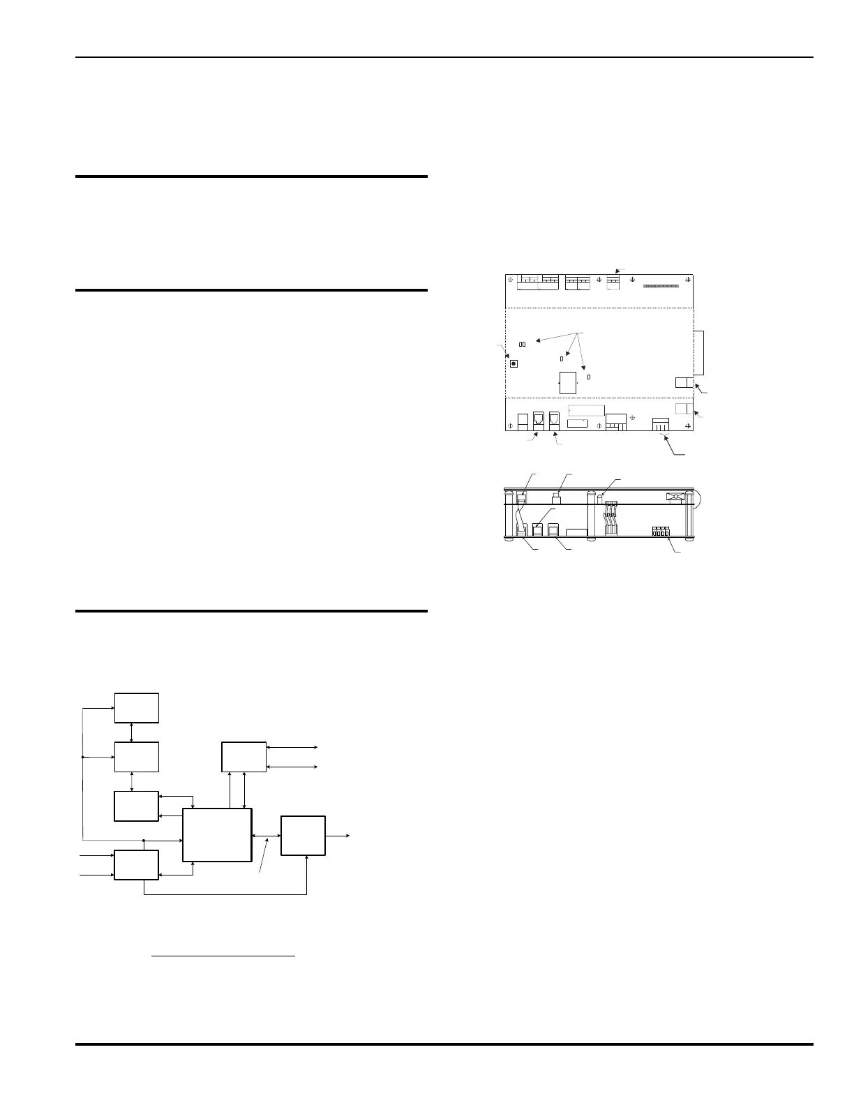
3-3.1 Central Control Module
The Central Control Module (CCM) contains the main cen-
tral processing unit, real-time clock, watch dog timer and
RS-232 serial communication input/output ports. The CCM
controls the operation and supervision of all the system
modules and software within the PEGAsys LV system. It
receives loop device data from the RX/TX module, pro-
cesses the data based on pre-programmed instructions
and transmits output commands to the output circuits, field
devices and display module(s). (See Figure 3-2)
0V
PORT
DISP
PRINT
PORT
PORT
JK1
JK2
0V
24V 5V
PLG1
P. C .
DISPLAY
5V
JK3
1
BT1
JP2
PLG2
SOUNDER 2
JP4
SW1
JP3
TB4
TB5
SOUNDER 1
-
REP 1
+
A
-
REP 2
B
+
+
A
-
JP1
VOLT FREE RELAYS
C
TB1
TB2
+
B
-
NO NO
1
NC C
2
NC
TB3
NC
V/F RELAY
FAUL T
NO C
FLT
SUPPLY
FLT
EARTH
24V
0V
TB6
JK4
RX/TX
PORT
JK5
PORT
I/O
To External
Printer
CCM Reset
Button
To Remote P.C. For
Programing
24 Vdc From
Power Supply
To RX/TX
Loop Controller
To I/O Modules and
Power Supplies
See Note 1
Note 1: The trouble relay
contacts are shown in the
unpowered state.
Note 2: Jumpers JP1-JP4 are
used to configure MP01 to be
signaling (default) or releasing
outputs. Refer to Appendix I,
for further details.
SKT1
See Note 2
DISPLAY ASSEMBLY
Display Reset
Switch
PLG2
JK1
JK2
PLG3
SW1
PLG2
JK3
PLG1
PRINT PORT
DS1
0V
24 VDC
EARTH FAULT
SUPPLY FAULT
TB6
BUZZER
Processor
Port
Display
Port
PC Port
Display Trouble
LED
24VDC From
Power Supply
Figure 3-2. Central Control Module, Details
The CCM provides two RS-232C serial ports for program-
ming and monitoring the PEGAsys LV system. These ports
accept six-wire RJ-12 modular connectors. The PCS pro-
gram is used to interface to the system for programming
purposes. A multi-level password scheme protects the sys-
tem from unauthorized access.
The real-time clock provides the CCM with the ability to
display the current time and date on the system LCD and
control the system with time-based programming.
Internal diagnostics enhance the troubleshooting ability of
the system. For example, microprocessor failure, memory
failure, RS-232 port troubles, etcetera.
Two individually programmable signal output circuits (MP1
and MP2) can be used for signaling devices (horns,
strobes, bells) and allow up to 2.0 Amps of 24 Vdc power.
One of the two outputs is programmable for releasing so-
lenoid type suppression equipment (Agent and Sprinkler
type systems).
Two individually programmable relay outputs (MP3 and
MP4) are provided on the CCM for controlling building func-
tions during alarm occurrences. These relay outputs are
activated through the EOC programming which allows sys-
tem inputs to be related to system outputs. Each of these
relays have Form C contacts, rated at 1 A, 30 Vdc.