April 2003 76-000000-001
PEGAsys™ LV
2-5 (2-6 blank)
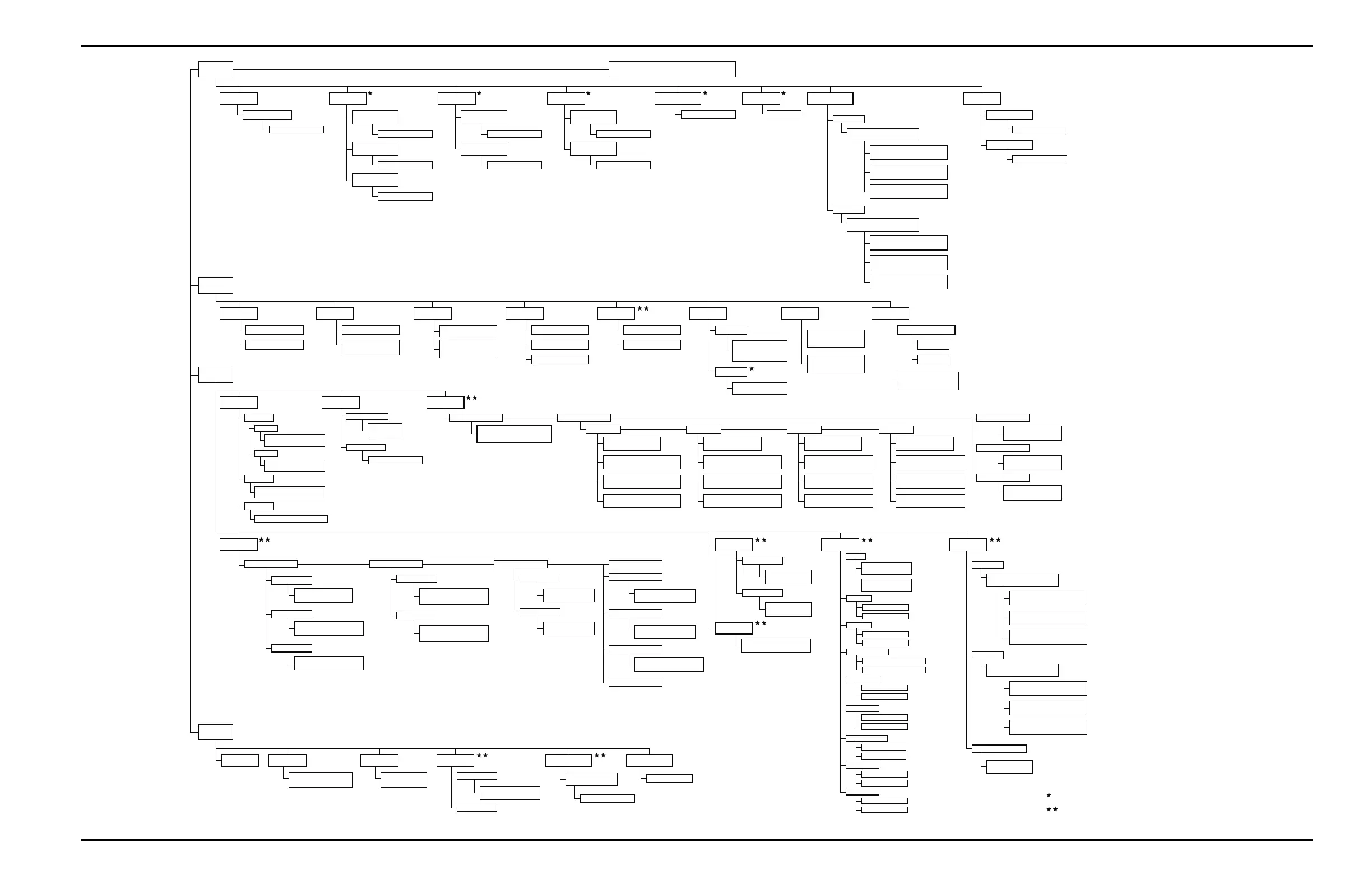
Figure 2-2. PEGAsys LV Menu Structure
1. Isolate
1. Loop Devices
Devices from ____ to ____
1. Isolate 2: De-Isolate
2. Signal Outputs
1. Signal Modules
SG*_:__ to SG*_:__
2. Release Modules
RS*_:__ to RS*_:__
3. Main Processor
MP*_ to MP__
1. Isolate 2: De-Isolate
1. Isolate 2: De-Isolate
1. Isolate 2: De-Isolate
3. Relay Outputs
1. Relay Modules
RY*_:__ to RY*_:__
2. Main Processor
MP*_ to MP__
1. Isolate 2: De-Isolate
1. Isolate 2: De-Isolate
4. Release Outputs
1. Release Modules
AR*_ to AR__
2. Main Processor
MP__
1. Isolate 2: De-Isolate
1. Isolate 2: De-Isolate
5. City-Tie Output
1. Isolate 2: De-Isolate
6. Digital I/O
Not Available
7. Control Modules
1. Isolate
Isolate Control / Display Modules
1: ATM 2: RDCM 3: RDM *
1: Enter the ATM Number to Isolate
ATM: *_
2: Enter the RDCM Number to Isolate
RDCM: *_
3: Enter the RDM Number to Isolate
RCM: *_
2. De-Isolate
De-Isolate Control / Display Module
1: ATM 2: RDCM 3: RDM *
1: Enter the ATM Number to De-Isolate
ATM: *_
2: Enter the RDCM Number to De-Isolate
RDCM: *_
3: Enter the RDM Number to De-Isolate
RCM: *_
8. Global Isolate
1. Inputs
2. Outputs
1. Isolate 2: De-Isolate
1. Isolate 2: De-Isolate
2. List
2. Control Module
List Control / Display Modules
1. ATM 2. RDCM 3. RDM :*
1. Isolated Devices
1. Loop Devices
2. System Outputs
2. Event Buffer
1. All Events
2. Range of Events
List Range of Events
From *_-__-__ to __-__-__
3. Detector Level
1. Single Detector
Enter Detector Address *___
2. Detector Range
Enter Range
From *___ to ____
4. Active Events
1. Alarm Events
2. Supervisories
3. Troubles
5. Programming
1. EOC Program
2. RTC Program
6. Assignments 7. Voltages
1. Line Voltage
Display Line Voltages
Devices From *___ to ____
2. 9 Volt
Display 9-Volt Levels
Devices From *___ to ____
8. More Options
1. Network
1. This Node
2. Network Node
3. Set
2. Det Sen / AAM Conf.
1. Time / Date 2. Printer Control
1. Internal Printer
2. External Printer
Menu Function
Not Available
1. Isolate 2: De-Isolate
3. Devices
1. Device Address Change
Set Loop Device Address
Present Loop Device Address *_ _ _
Set Target Loop Address *_ _ _
1. Ionization
Set Detector Sensitivity
Detectors From *___ to ____
Set Detector Sensitivity
1: Open Area 2: Hi Vel 3: Duct 4: Old Det. *
Set Detector Sensitivity
Pre-Alarm Level *._ (0.5 - 1.5) %/Ft.
Set Detector Sensitivity
Alarm Level *._ (0.5 - 1.5) %/Ft.
2. Photoelectric
Set Detector Sensitivity
Detectors From *___ to ____
Set Detector Sensitivity
1: Open Area 2: Hi Vel 3: Duct 4: Old Det. *
Set Detector Sensitivity
Pre-Alarm Level *._ (0.2 - 3.5) %/Ft.
Set Detector Sensitivity
Alarm Level *._ (0.5 - 3.5) %/Ft.
3 Thermal
Set Detector Sensitivity
Detectors From *___ to ____
Set Detector Sensitivity
1: 50 Ft. 2: 70 Ft. *
Set Detector Sensitivity
Pre-Alarm Level *__ (80 - 145)
Set Detector Sensitivity
Alarm Level *__ (135 - 155)
4 Alarmline
Set AAM Configuration
Detectors From *___ to ____
Set AAM Configuration
Switch Setting 1 to 16 *_
Set AAM Configuration
Pre-Alarm 1: ON 2: OFF *
Set AAM Configuration
Alarm 1: Normal 2: Overheat *
3. Registration
Device Registration
Devices From *___to____
4. De-Registration
5. Blink Control
Device De-Registration
Devices From *___to____
Program Device Blink Control
Devices From *___to____
4. Programming
1. Day / Night
Activate Day/Night Operation
1. Activate 2. De-Activate *
1. Set Detectors
Set Day Period (Now 08:00)
Day Period Start *_:__ (24 hour clock)
2. Set Periods
Set Day/Night Detectors
Detector Address *___ to ____
3. Activate
2. Passwords
1. Owner's
2. Installer's
Change Owner Password
Enter New Password *_______
Re-Enter New Password *________
Change Installer Password
Enter New Password *_______
Re-Enter New Password *________
3. Real Time Control
1. Enable RTC
2. Disable RTC
RTC Enable Program Line
RTC Line Number *__
RTC Disable Program Line
RTC Line Number *__
4. AutoLearn
5. Alarm Verification
7. Clear Events
8. Resynch. Network
Assign Alarm Verification
Detector Address *___ to ____
6. Positive Alarm Sequence
Assign Positive Alarm Sequence
Detector Address *___ to ____
Clear Event Buffer
1. Clear Events 2. Cancel *
5. Loops
6. Global Ack
1. Enable Loop
2. Disable Loop
Enable Loop
Enter Loop Number *
Disable Loop
Enter Loop Number *
Enable / Disable Global Acknowledge
1. Enable 2. Disable *
7. Network
1. Style
1. Ch1 Enable/Disable
1: Enable 2: Disable *
2. Ch2 Enable/Disable
1: Enable 2: Disable *
2. Node No.
1. Node No. (1 to 32)
2. Stand Alone (0)
3. Group
1. Group No. (1 to 32)
2. Not Grouped (0)
4. Add/Remove Nodes
1. Add Node # __ to Node # __
2. Remove Node # __ to Node # __
8. Control Modules
1. Register
Register Control / Display Module
1: ATM 2: RDCM 3: RDM *
1: Enter the ATM Number to Register
ATM: *_
2: Enter the RDCM Number to Register
RDCM: *_
3: Enter the RDM Number to Register
RCM: *_
2. De-Register
De-Register Control / Display Module
1: ATM 2: RDCM 3: RDM *
1: Enter the ATM Number to De-Register
ATM: *_
2: Enter the RDCM Number to De-Register
RDCM: *_
3: Enter the RDM Number to De-Register
RCM: *_
6. Silence Events
1. Node No. (1 to 64)
2. Stand Alone (0)
7. Log Events
1. All Events
2. Group only
8. Resync Period
1. 0
2. 1 - 60000 Minutes
9. Isolate
1. Isolate Node
2. De-Isolate Node
5. Reset Event
1. Enable Network Reset
2. Disable Network Reset
1. Lamp Test 2. Loop Devices
Start Device Test
Test Devices From *___ to ____
3. Battery Test 4. Walk Test 5. Alarm Simulation Test
4. Test
Battery Test
Battery Test on PS* _
1. Start Walk Test
Start Devices Walk Test
Detector Address *___ to ____
2. Stop Walk Test
Alarm Simulation Test
Detector Address *____
6. Alarm Drill
1. Drill 2: Exit *
Enter Password
1. Activate 2: De-Activate *
1. Set Time
1. AM / PM
2. Military
Set Time (AM / PM)
Enter the Time *_:__ (HH:MM)
Set Time (Military)
Enter the Time *_:__ (HH:MM)
2. Set Date
Set Date
Enter the Date *_-__- __ (MM-DD-YY)
3. Battery
1: Batt Disp Enable 2: Batt Disp Disable
Option not supported in PEGAsys LV
Level-2 (Installer) Password required.
Legend
1. Loop Devices
2. I/O Modules
Loop Device Assignments
Loop No. *
Dev Type Message
Module Style Message
3. Reset ATM / RDCM / RDM
Reset Control Module
1: Reset 2: Exit *