A-4April 2003 76-100016-002
PEGAsys™ LV
A-5.1 Power Requirement Example
The following power calculations will be based on a the system configuration listed below:
Central Control Panel (CCP) with Field Devices:
• Central Control Module
• Ten (10) Ionization Detectors
• One (1) RX/TX Module
• Twenty (20) Photoelectric Detectors
• One (1) Power Supply Module
• Ten (10) Heat Detectors
• Six (6) Addressable Contact Input Devices
• Four (4) Addressable Contact Output Devices
• Ten (10) Signaling Devices, connected to MP1 of the CCM, with a total current of 0.75A
A-5.2
AC Branch Current Calculation Example
This example is based on the system specified in the previous paragraph. This system current calculation is for a 120 Vac
main feed. Refer to Paragraph A-1 for additional information.
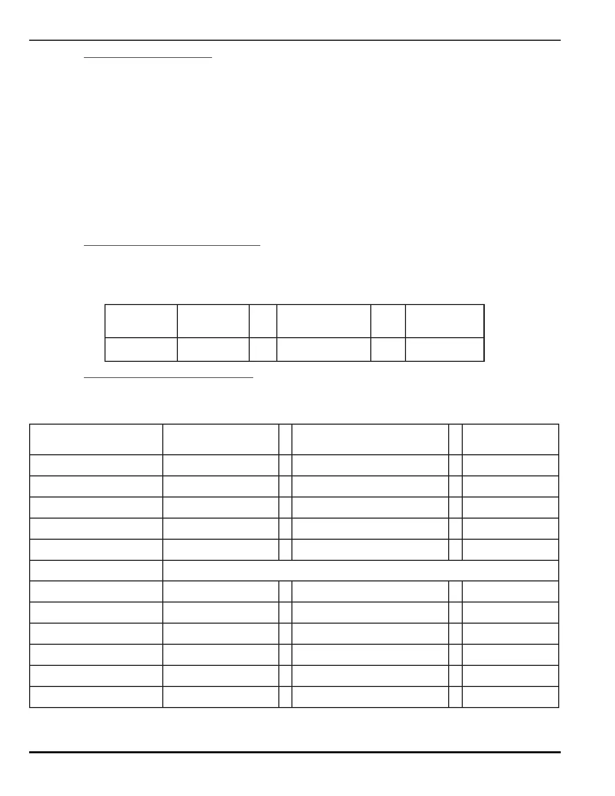
Table A-7. AC Branch Calculation Example
epyTeciveD
forebmuN
seciveD
warDtnerruC
)spmA(
tnerruClatoT
lenaPlortnoC1X9.1=9.1
A-5.3 Main Power Supply Loading Examples
This example is based on the same system as above. Refer to Paragraph A-2 for additional information.
Table A-8. Standby or Non-Alarm Power Requirement Calculation
eciveD/eludoM)spmA(tnerruCybdnatSmetsyS/eludoM
ybdnatSmumixaM
)spmA(tnerruC
eludoMlortnoClartneC070.0X 1 =070.0
eludomXT/XR530.0X 1 =530.0
rotinoMylppusrewoP060.0X 1 =060.0
A5.1xaM,1tuptuOyrailixuAX=
A5.1xaM,2tuptuOyrailixuAX=
SECIVEDDLEIF
rotceteDnoitazinoI004000.0X 01=400.0
rotceteDcirtceleotohP004000.0X 02=800.0
rotceteDtaeH004000.001400.0
tupnItcatnoCelbasserddA013000.0X 6 =4200.0
tuptuOtcatnoCelbasserddA033000.0X 4 =6100.0
daoLybdnatSrofnmuloCmuS=
spmA521.0