1-2August 1999 76-100016-001
PEGAsys
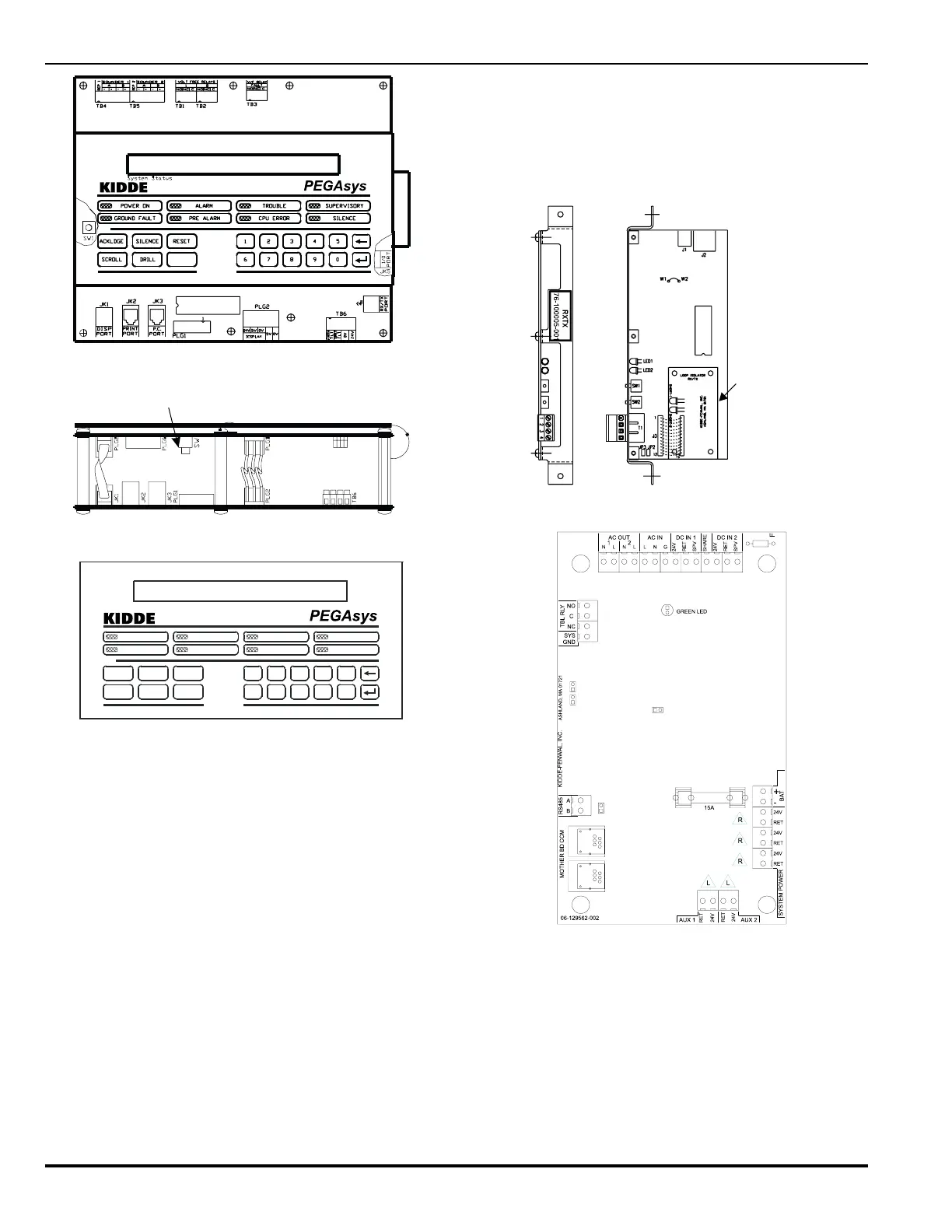
Intelligent Suppression Control/Fire Alarm System
Display Reset Switch
Figure 1-2. Central Control Module (CCM)
System Status
ALARM
GROUND FAULT
POWER ON
PREALARM
TROUBLE
CPU ERROR
SUPERVISORY
SILENCE
SILENCE
ACKLDGE RESET
SCROLL DRILL
2
DRILL
14
3
5
6
7890
Figure 1-3. Display Module Assembly
1-2.3 Receiver/Transmitter Module (RX/TX)
The RX/TX functions as the hardware & software interface be-
tween the field devices and the CCM. The RX/TX receives con-
trol requests from the CCM and establishes communications
with the field devices. The RX/TX receives status changes from
the field devices and reports these changes to the CCM. The
RX/TX shown in Figure 1-4 is capable of communicating with
up to 255 intelligent devices and complies with the wiring re-
quirements of NFPA Style 4, 6 & 7 (with the use of the loop
isolator device). Style 4 initiation circuit wiring will permit “T”
tapping, or branch circuitry.
1-2.4 Power Supply/Charger Assembly
The power supply/charger assembly (P/N 76-100009-010) is
comprised of a printed circuit board (PCB) assembly and a AC/
DC switching power supply unit. The switching power supply
unit provides 4 amps of 24 VDC from the 120/240 VAC input
power. The PCB assembly is a microprocessor based unit which
provides the system with:
• Battery charging and supervision
• AC power supervision
• 24 VDC supervision
• Battery load test
• 24 VDC ground fault detection (+/-)
• Auxiliary 24 VDC outputs
Loop Isolator
for Style 7
Figure 1-4. Receiver/Transmitter Module (RX/TX)
Figure 1-5. Power Supply/Charger Assembly
1-2.5 Basic Motherboard
The basic I/O motherboard assembly (P/N 76-100007-001) is
an assembly which can accept up to 8 I/O module circuit board
assemblies. The motherboard is mounted to the back of the
system enclosure and /or the auxiliary enclosures. It distributes
the system 24 VDC power and I/O bus communications to the I/
O modules. The I/O bus communications are provided by a RJ-
12 (flat phone cable) style connection. The 24 VDC is provided
by the system power supply via a 2-conductor wiring harness.