August 1999 76-100016-001
PEGAsys
Intelligent Suppression Control/Fire Alarm System
3-2
3-3 FUNCTIONAL DESCRIPTIONS
The functional descriptions will describe each device or mod-
ule depicted in Figures 3-1 and 3-2.
3-3.1 Central Control Module
The Central Control Module (CCM) is available in two versions,
P/N 76-100008-501 for single-loop and P/N 76-100008-600 for
multi-loop. Figure 3-3 contains the main central processing unit,
real time clock, watch dog timer and RS-232 serial communica-
tion input/output ports. The CCM controls the operation and
supervision of all the system modules and software within the
PEGAsys system. It receives loop device data from the RX/TX
module, processes the data based on pre-programmed instruc-
tions and transmits output commands to the output modules,
field devices and display module(s).
The CCM provides two RS-232C serial ports for programming
and monitoring the PEGAsys system. These ports accept 6-
wire RJ-12 modular connectors. The PCS program would be
used to interface to the system for programming purposes. A
multilevel password scheme protects the system from unau-
thorized access.
The real time clock provides the CCM with the ability to display
the current time & date on the system LCD and control the sys-
tem with time based programming.
Internal diagnostics enhance the troubleshooting ability of the
system, examples: microprocessor failure, memory failure, RS-
232 port troubles, etc..
Two individually programmable signal output circuits (MP1 &
MP2) provided can be used for signaling devices (horns, strobes,
bells) and allow up to 2.0 amps of 24 VDC power. One of the
two outputs is programmed for releasing solenoid type suppres-
sion equipment (Agent and Sprinkler type systems).
Two individually programmable relay outputs (MP3 & MP4) are
provided on the CCM for controlling building functions during
alarm occurrences. These relay outputs are activated through
the EOC programming which allows system inputs to be re-
lated to system outputs. Each of these relays have Form C style,
rated at 1A, 30VDC.
One non programmable trouble relay is supplied which is nor-
mally powered (24 VDC) and will transfer on any system trouble,
supervisory, pre-alarm and complete power off condition. Form
C contact rating 1A at 30VDC. Refer to DWG. No. 06-235443-
001 in Appendix I for further installation details.
An event history buffer is provided on the CCM which will store
1024 entries for single-loop and 6100 entries for multi-loop of
system event information and allow the operator to retrieve this
information for review of system operation. The PCS program
provides the ability to download, store and print all or a portions
of the Event History Buffer.
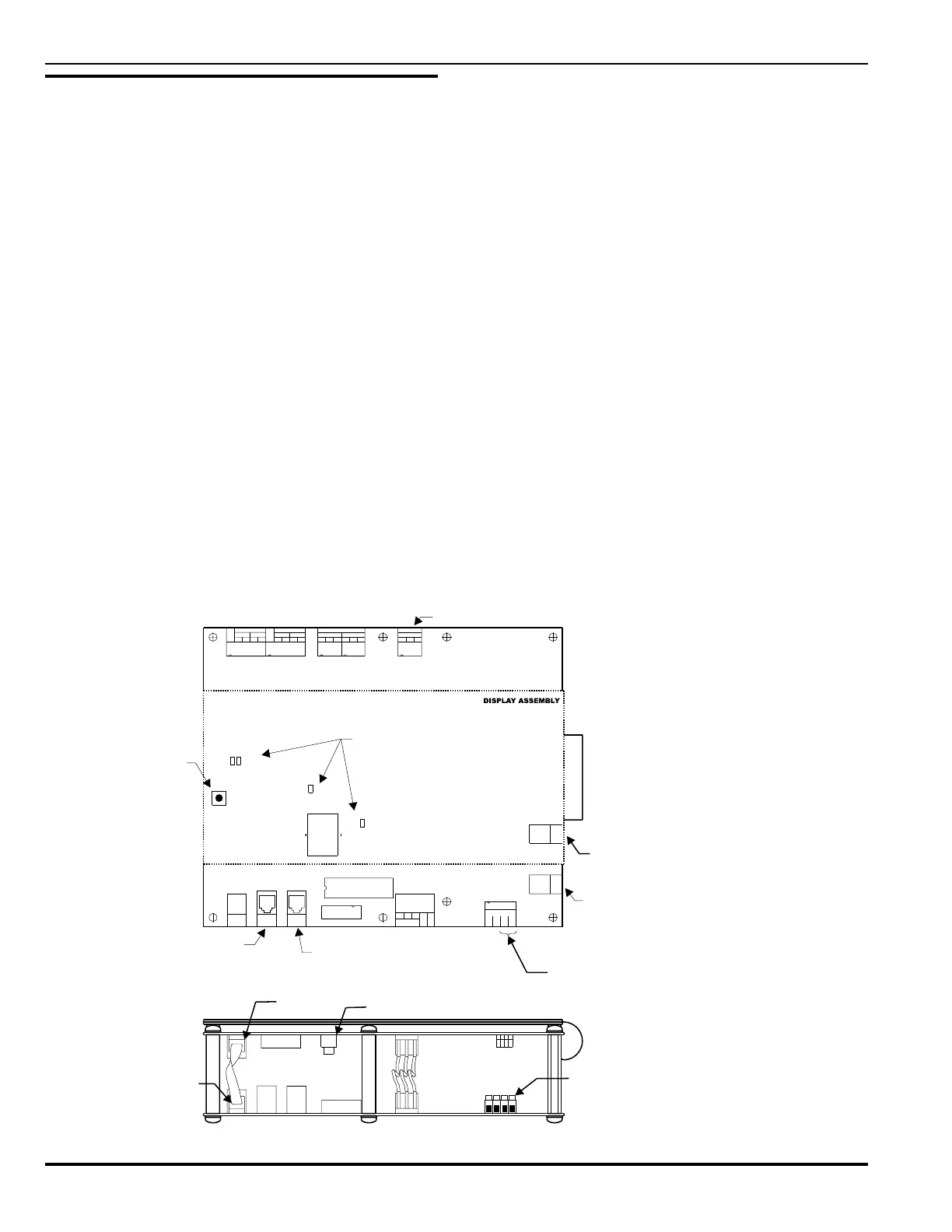
Figure 3-3. Central Control Module, Details
0V
JK1
JK2
PLG2
JK3
PLG1
PLG6
SW1
PLG2
PLG3
PORT
DISP
PRINT
PORT
PORT
JK1
JK2
0V
24V 5V
PLG1
P. C .
DISPLAY
5V
JK3
1
BT1
JP2
PLG2
SOUNDER 2
JP4
SW1
JP3
TB4
TB5
SOUNDER 1
-
REP 1
+
A
-
REP 2
B
+
+
A
-
JP1
VOLT FREE RELAYS
C
TB1
TB2
+
B
-
NO NO
1
NC C
2
NC
TB3
NC
V/F RELAY
FAU LT
NO C
TB6
FLT
SUPPLY
FLT
EARTH
24V
0V
TB6
JK4
RX/TX
PORT
JK5
PORT
I/O
To External
Printer
CCM Reset
Button
To Remote PC For
Programing
To Remote PC For
Programing
24VDC From
Power Supply
To RX/TX
Loop Controller
To I/O Modules and
Power Supplies
To I/O Modules and
Power
Supplies
Display
Port
Proc.
Port
Display Reset
24VDC From
Power Supply
See Note 2
See Note 2See Note 2
See Note 1
Note 1: The trouble relay
contacts are shown in the
unpowered state.
Note 1: The trouble relay
contacts
are shown in the
unpowered
state.
Note 2: Jumpers JP1-JP4 are
used to configure MP01 to be
signaling or releasing (default)
outputs. Refer to Dwg. No.
06-235443-001, in Appendix I,
for further details.
Note 2: Jumpers JP1-JP4 are
used
to configure MP01 to be
signaling
or releasing (default)
outputs.
Refer to Dwg. No.
06-235443-001,
in Appendix I,
for
further details.