1-3 August 1999
Intelligent Suppression Control/Fire Alarm System
PEGAsys
76-100016-001
The I/O motherboard mounts to standoffs on the back of the main
and expansion enclosures with screws provided.
Figure 1-6. Basic I/O Motherboard
1-2.6 Multi-Loop Motherboard
The multi-loop I/O motherboard assembly (P/N 76-100017-001)
is an assembly which can accept up to 8 RX/TX modules and
provide connections for up to 7 I/O module circuit board as-
semblies. The ML motherboard is mounted to standoffs on the
back of the main system enclosure. It distributes system 24
VDC power, CCM-RX/TX communications for up to 8 RX/TX
modules and I/O bus communications to the I/O modules. The
I/O bus communications are provided by a RJ-12 (flat phone
cable) style connection. A single RJ-12 connection connects
the ML motherboard to the CCM for RX/TX communications.
The 24 VDC is provided by the system power supply via a 2-
conductor wiring harness.
Figure 1-7. Multi-Loop I/O Motherboard
1-2.7 Input/Output Modules
The optional input/output modules allow the PEGAsys system
to interface with external auxiliary devices. These auxiliary de-
vices can be audible/visual signal devices, HVAC systems, el-
evator recall, power shut down, remote annunciators, agent/
sprinkler release system and any other control type input or
output which may need to be interfaced to the system.
The input and output modules plug into the motherboard as-
sembly located on the back plate of the system enclosure. Each
I/O module occupies one slot in the motherboard assembly which
has 8 slots available. The I/O modules and the CCM communi-
cate over the RS-485 based I/O bus, which uses a 6-conductor
phone type cable to connect the CCM to the motherboard.
The PEGAsys single-loop panel has the ability to support a
maximum of 16 I/O modules, in any combination. However, no
more than 8 of any one type of module can be used. If using a
City-Tie module, the limit is one per system.
The PEGAsys multi-Loop panel has the ability to support a maxi-
mum of 23 I/O modules, in any combination, on the system.
However, no more than 8 of any one type module can be used.
If using a City-Tie module, the limit is one per system.
The following paragraphs describe each available I/O module
in greater detail.
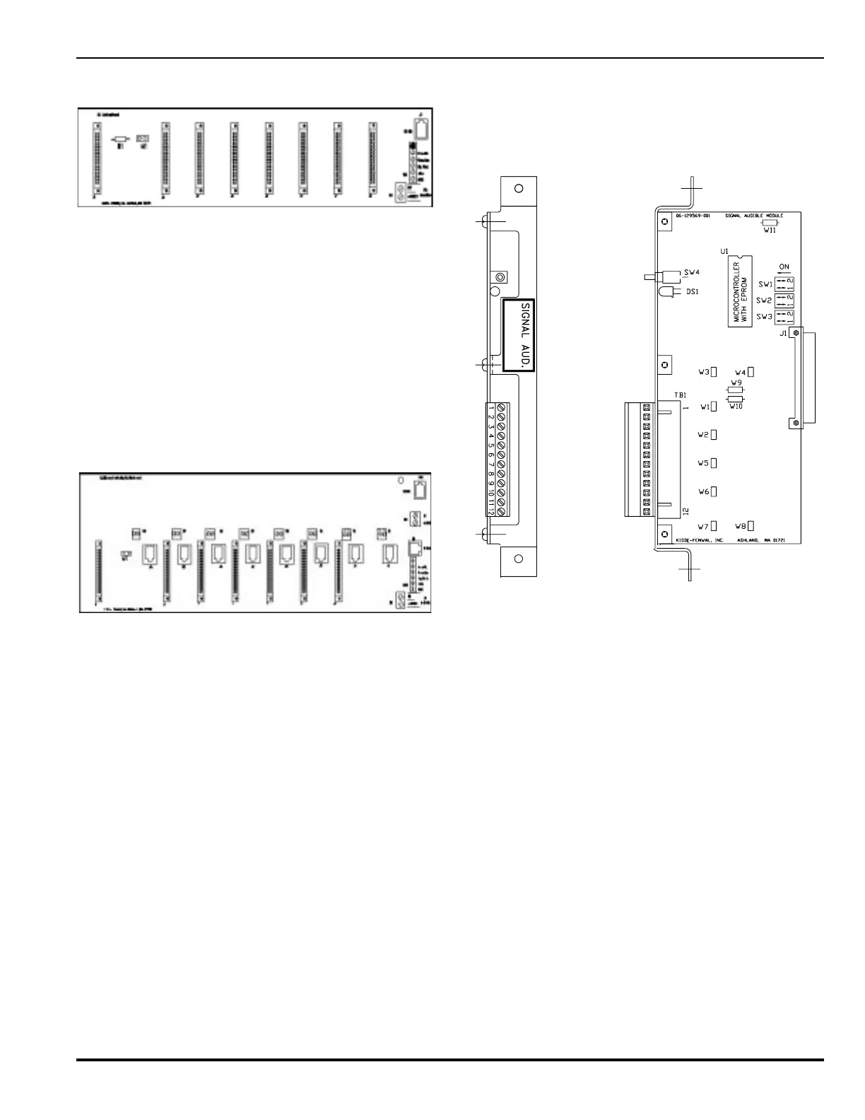
1-2.7.1 SIGNAL OUTPUT MODULE
The PEGAsys panel has the capacity for a maximum of (8) Alarm
Sounder/Signal Output cards, thus providing 32 possible sig-
nal circuits. Each Alarm Sounder/Signal Output card, Figure 1-
8, is equipped with supervised 24 VDC outputs which can
operate as Style “Y” or Style “Z” indicating circuits.
76-100003-001
Figure 1-8. Signal Output Module
1-2.7.2 RELAY OUTPUT MODULE
The PEGAsys panel has the capacity for a maximum of 8 Aux-
iliary Relay Output cards, allowing up to 32 relays. Each Auxil-
iary Relay Output card is equipped with four (4), Form C,
dry-contact relay outputs. The ability to isolate an individual relay
output is provided through the system operator menu.